EasyManuals Logo

Hypertherm Powermax65 SYNC Troubleshooting Guide

Hypertherm Powermax65 SYNC
180 pages
To Next Page IconTo Next Page
To Previous Page IconTo Previous Page
Page #119 background imageLoading...
Page #119 background image
Do System Tests to Identify Defective Components
5
Powermax65/85/105 SYNC Troubleshooting Guide 810430 11 9
10. Disconnect the DSP PCB from the power PCB by removing the 2 mounting screws.
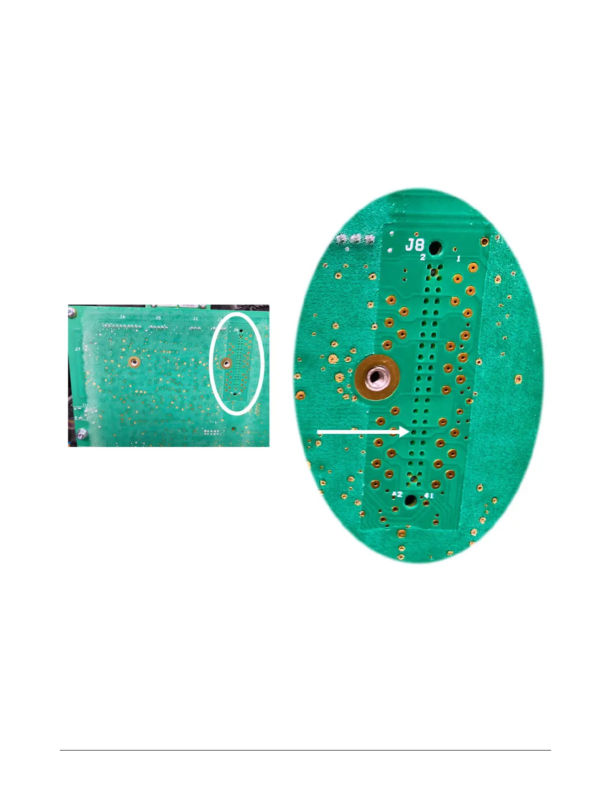
11 . Measure the resistance between pin 2 on J4 or J6 on the power PCB and pin 32 on J8. Refer to
Figure 33. Is the voltage approximately 100 ohms ()?
If yes, replace the DSP PCB.
If no, replace the power PCB.
Figure 33 – Pin 32 on J8 on power PCB

Table of Contents

Other manuals for Hypertherm Powermax65 SYNC

Questions and Answers:

Question and Answer IconNeed help?

Do you have a question about the Hypertherm Powermax65 SYNC and is the answer not in the manual?

Hypertherm Powermax65 SYNC Specifications

General IconGeneral
BrandHypertherm
ModelPowermax65 SYNC
CategoryWelding System
LanguageEnglish

Related product manuals