Connect for Communication
XPR300 Instruction Manual 809480 195
5. Connect the ohmic wire from the ohmic relay to J4 pin 2 on the ohmic PCB in the torch
connect console.
6. Connect the ohmic wire to the PCB connection for ohmic inside the lifter.
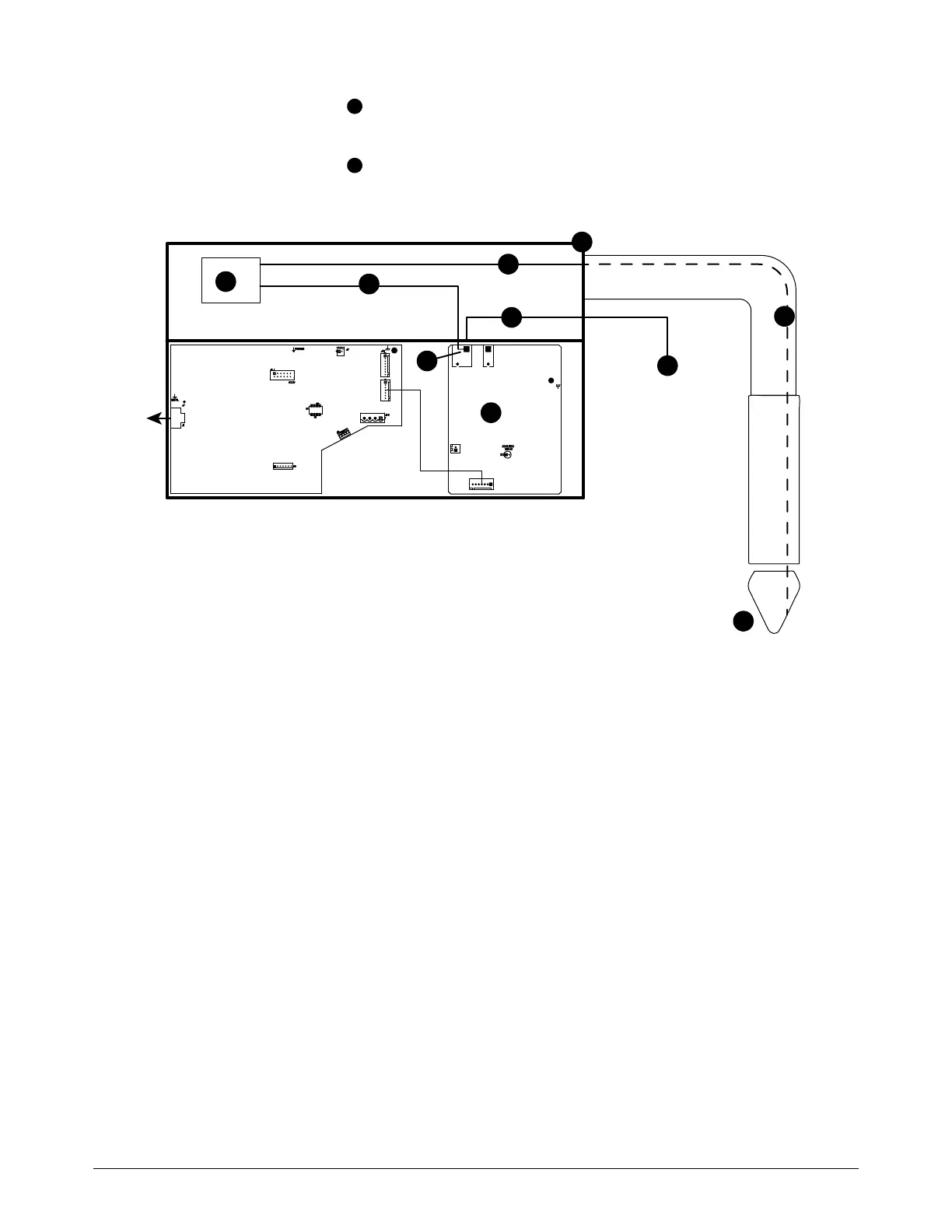
Figure 55 – Example external ohmic diagram
1 Torch
2 Ohmic wire, inside torch and torch lead
3 Torch connect console
4 Ohmic wire, torch receptacle to ohmic relay
5 Ohmic relay
6 Ohmic wire, ohmic relay to J4
7 Ohmic PCB
8 Ohmic wire, J4 to lifter or third party ohmic
circuit
9 Torch lifter or third party ohmic circuit
10 Pin 1 and pin 2 on J4 are connected in the
ohmic PCB