Diagnostics and Troubleshooting
XPR300 Instruction Manual 809480 345
7. Examine the work lead. Replace it if you find damage or excess wear.
8. Examine the pilot arc circuit (plasma power supply to gas connect console, to torch connect
console, to torch receptacle).
a. If the pilot arc wire is damaged, replace the damaged item.
b. If the pilot arc wire is not damaged, replace the torch and receptacle.
9. Release the pilot arc relay and measure the ohms between the nozzle and workpiece. The
acceptable range is 9,000 – 11,000 ohms. If the ohms value is low (approximately 5,000 ohms
or less), examine the pilot arc circuit (power supply to gas connect console, to torch connect
console, to torch receptacle). Look for insulation damage and short circuits to ground.
How to measure resistance from thermistors
1. Use a digital multimeter to measure the resistance from each thermistor wire, based on the
following connector-pin locations:
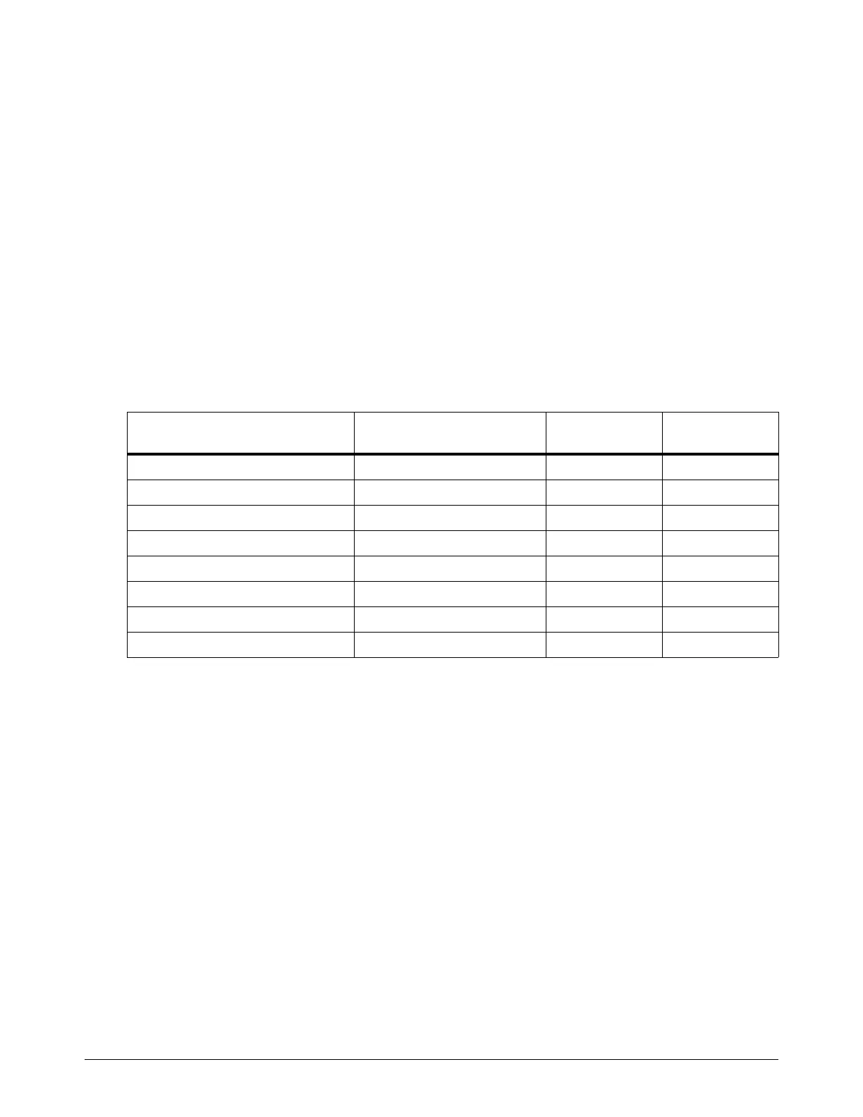
2. Look for a resistance value that is outside of the minimum or maximum in Table 39:
Thermistor location
Location of thermistor
wires/connector
1st connector
pin
2nd connector
pin
Inductor 1A PCB 1 J1.4 pin 3 J1.4 pin 4
Inductor 1B PCB 1 J1.4 pin 5 J1.4 pin 6
Inductor 2A PCB 1 J1.4 pin 7 J1.4 pin 8
Inductor 2B PCB 1 J1.2 pin 1 J1.2 pin 2
Transformer PCB 1 J1.4 pin 1 J1.4 pin 2
Chopper 1 PCB 2 J9 pin 1 J9 pin 2
Chopper 2 PCB 3 J9 pin 1 J9 pin 2
Coolant temperature PCB 1 J1.2 pin 7 J1.2 pin 8