Qualifications and Requirements
XPR300 Instruction Manual 809480 69
11 . For XPR cutting systems, the coupler on the pilot arc and coolant hose set assembly must be
connected firmly to the gas connect console and torch connect console collars. Make sure to
tighten the clamp. The collar on the torch lead must be connected firmly to the torch sleeve.
Make sure to tighten the clamp. Connect a ground lead (10 AWG) to the flat terminal on the
torch mounting sleeve.
12. The torch holder and the torch breakaway mechanism – the part mounted to the lifter, not the
part mounted to the torch – must be connected to the stationary part of the lifter with copper
braid at least 12.7 mm (0.5 inches) wide. A separate cable must run from the lifter to the gantry
ground bus bar. The valve assembly should also have a separate ground connection to the
gantry ground bus bar.
13. If the gantry runs on rails that are not welded to the table, then each rail must be connected with
a ground cable from the end of the rail to the table. The rail ground cables connect directly to
the table and do not need to connect to the table ground bus bar.
14. If you are installing a voltage divider board, mount it as closely as possible to where the arc
voltage is sampled. One recommended location is inside the plasma system enclosure. If a
Hypertherm voltage divider board is used, the output signal is isolated from all other circuits. The
processed signal should be run in twisted shielded cable (Belden 1800F or equivalent). Use a
cable with a braided shield, not a foil shield. Connect the shield to the chassis of the plasma
system and leave it unconnected at the other end.
15. All other signals (analog, digital, serial, and encoder) should run in twisted pairs inside a
shielded cable. Connectors on these cables should have a metal housing. The shield, not the
drain, should be connected to the metal housing of the connector at each end of the cable.
Never run the shield or the drain through the connector on any of the pins.
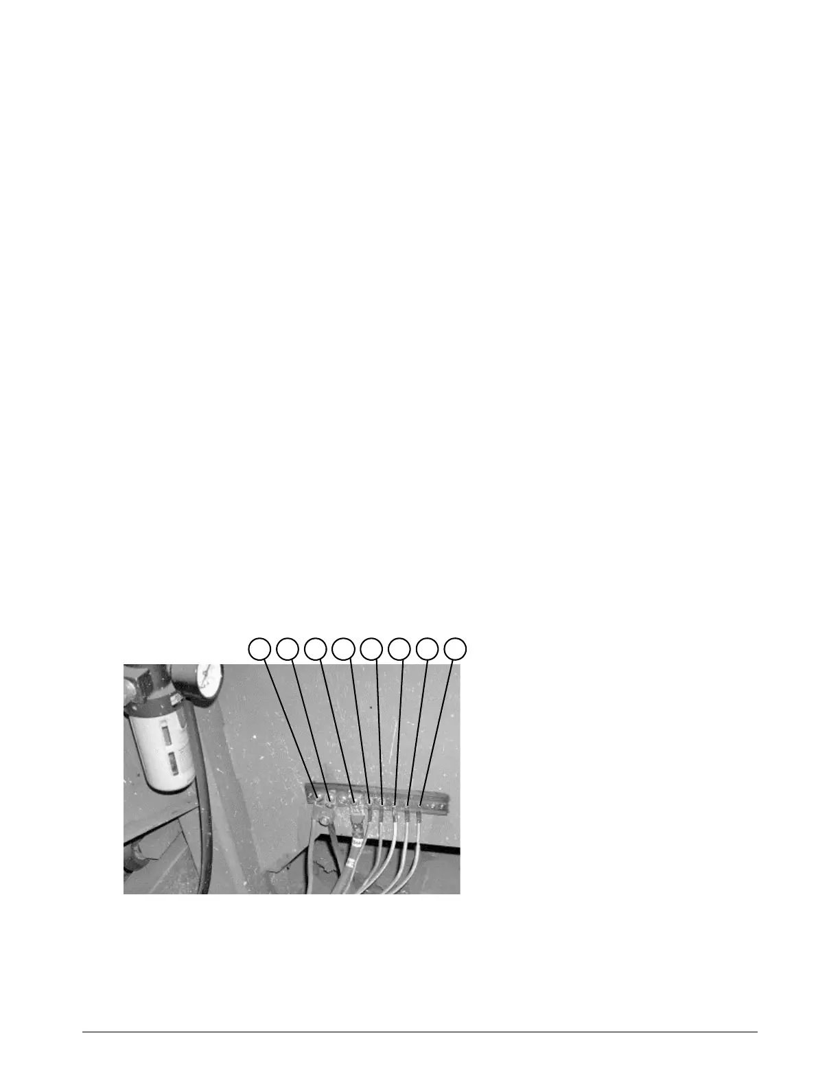
The following picture shows an example of a cutting table ground bus with an XPR cutting system.
The components shown here may differ from your system.
1 Gantry ground bus
2 Ground rod
3 Plasma system lead (+)
4 Gas connect console
5 CNC enclosure
6 Torch holder
7 Plasma system chassis
8 Torch connect console
1 2 3
4
5 6
7 8