3.4 Wiring connections (for connectors)
3-28
3. Wiring
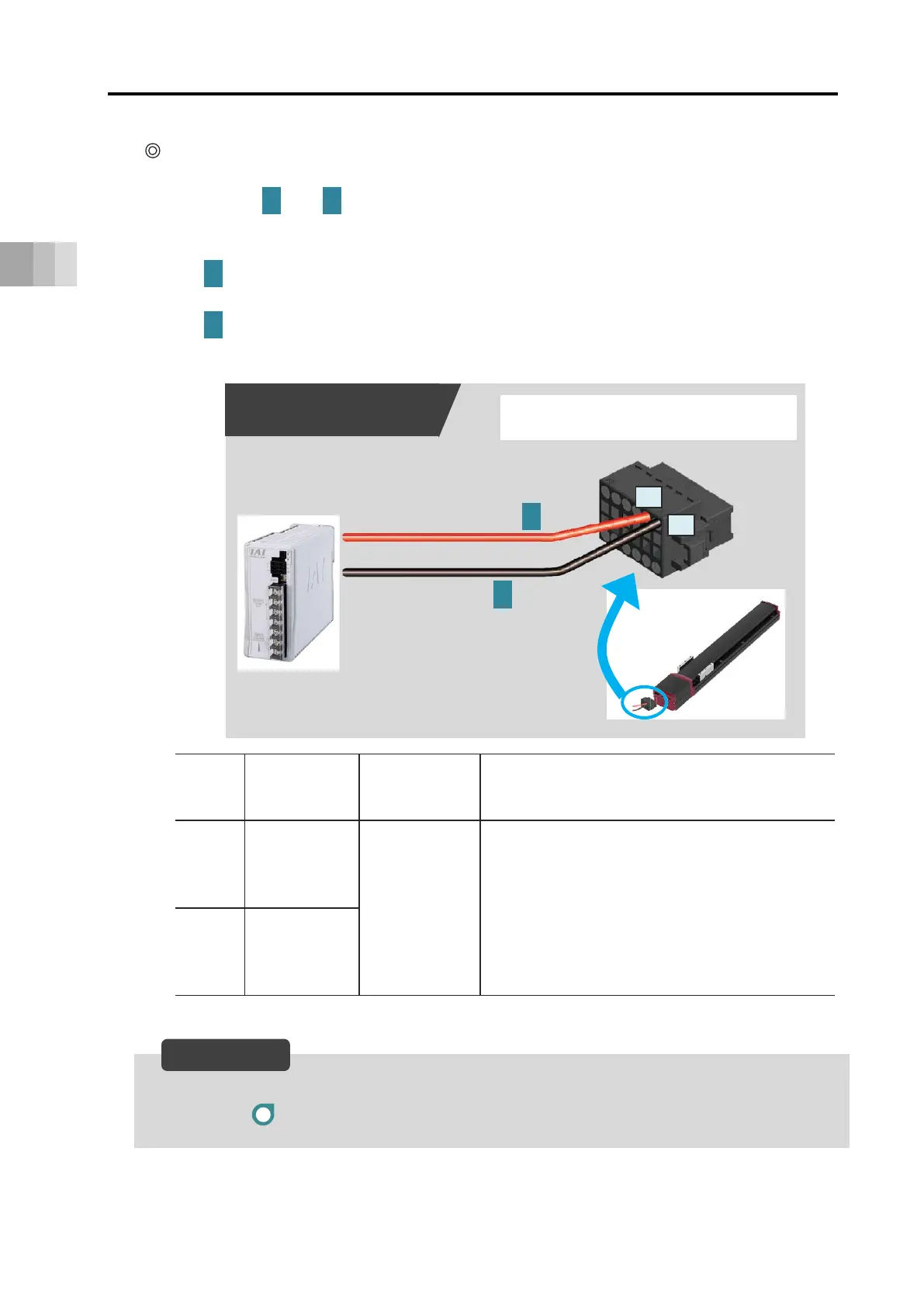
Two-circuit power supply specification TMD2 (Option)
Connect the power wiring to the power I/O connector.
Connect the and wiring to the connector terminal block while referring to the
connection diagram.
Connect the [A2] connector terminal and the +24 V (control) terminal of the 24 V DC
power supply.
Connect the [A1] connector terminal and the 0 V terminal of the 24 V DC power
supply.
By cutting off the 24 V (drive source) (PIN number B1), it turns to the stop condition.
→ Refer to Example for wiring actuator units and motor drive DC power supply PSA-200.
Pin
No.
Connector
nameplate
name
Compatible
wire
diameter
Required specifications
A2
24 V
(Control)
KIV 0.75 mm
2
(AWG18)
Control power voltage: 24 V DC ±10%
Control power capacity: 0.32 A
Brake power supply: 0.875 A
(when in overexcitation)
(Option)
When teaching pendant used:0.15 A
Wiring length: 10 m or less
A1 0 V
Reference
1 2
1
2
24 V DC power supply
connection diagram
Before starting connector wiring,
check the details on pages 3-30 to 31
Power I/O connector
A1
A2
0V
1
+24 V
2
 Loading...