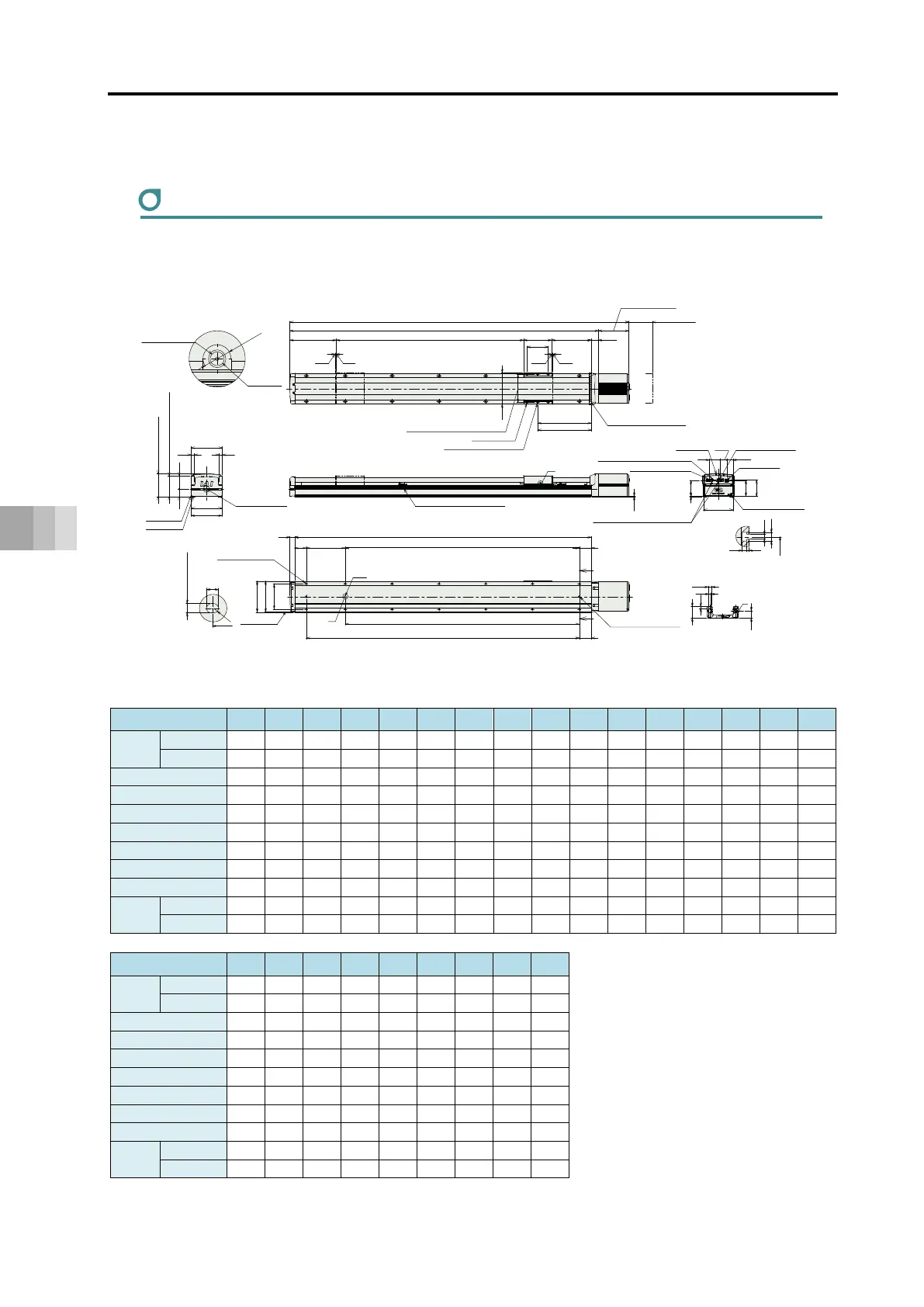
9.1 Slider type
9-2
9. External Dimensions
1.5
V
20
J
109
50 50C
50K
130
132
B
D×200P
Z
Z
Q
A
L
ST197.5
5 5
230
120
90
129.5 (W/o brake)
147.5 (With brake)
31.5168.5
228.5
134
120 (Reamed hole tolerance±0.02)
4-M8 Depth 20
2-φ8 H7 Reamed, depth 10
M.E.S.E.M.E.
32 58
132
130
(134)
14 14
125
1
69
68.4
68.5
26.5
28.4
46
φ
1
2
φ6
10
J
8
+0.015
0
φ14
φ9
50
8.5
32
P
(32)
4.3
7.3
1.8
4.3
*1 The battery charge status display LED turned on shows that power is charged inside the controller. Make sure to turn the power off
and confirm the LED is turned off before having a wiring work or inspection work in order to prevent electric shock.
(Note) After the home-return operation gets conducted, the slider should move to the mechanical end. Pay attention to interference to peripherals.
Must be 100 or more
Caution for interferrence to
workpiece attached to slider
O
p
e
n
i
n
g
Detailed view of V
Greasing port
Fitting diameter
Grease fitting for
ball screw/guide
(Same on opposite side)
HOME
M4 (For grounding connection)
Teaching port
Power I/O connector
Motor power connector
Connector Guard Attachment (M3)
Status LED
Battery charge status display LED *1
2-φ8 H7 Reamed, depth 10
(from base seat surface)
Cross section of Z-Z
Detail of counterbore for base installation
Detailed view of P
Details of T-shaped slot
(Dimension B range)
T-shaped slot: M4 (Both Sides)
Base datum surface
Oblong
hole
90 (Upper surface of slider)
Allowable moment
offset datum position
Da tum surfa ce
(Dimension B range)
From base seat
surface depth 10
Detailed view of Q
Details of base oblong hole
Base seat surface
96.7 (Total Height)
E-φ9 Thru,
φ14 Counterbore dept. 8.5
(from opposite side)
EC-S13X
M.E.: Mechanical end, S.E.: Stroke end, ST: Stroke
■ Dimensions and Mass by Stroke
Stroke 800 850 900 950 1000 1050 1100 1150 1200 1250 1300 1350 1400 1450 1500 1550
L
W/o Brake 1447 1497 1547 1597 1647 1697 1747 1797 1847 1897 1947 1997 2047 2097 2147 2197
With Brake 1465 1515 1565 1615 1665 1715 1765 1815 1865 1915 1965 2015 2065 2115 2165 2215
A 1317.5 1367.5 1417.5 1467.5 1517.5 1567.5 1617.5 1667.5 1717.5 1767.5 1817.5 1867.5 1917.5 1967.5 2017.5 2067.5
B 1266 1316 1366 1416 1466 1516 1566 1616 1666 1716 1766 1816 1866 1916 1966 2016
C 166 216 266 316 166 216 266 316 166 216 266 316 166 216 266 316
D 5 5 5 5 6 6 6 6 7 7 7 7 8 8 8 8
E 14 14 14 14 16 16 16 16 18 18 18 18 20 20 20 20
J 1000 1000 1000 1000 1200 1200 1200 1200 1400 1400 1400 1400 1600 1600 1600 1600
K 1166 1216 1266 1316 1366 1416 1466 1516 1566 1616 1666 1716 1766 1816 1866 1916
Mass
(kg)
W/o Brake 17.5 18.0 18.5 19.0 19.5 20.6 21.1 21.6 22.1 22.6 23.1 23.6 24.1 24.6 25.1 25.6
With Brake 18.1 18.6 19.1 19.5 20.0 21.2 21.7 22.2 22.7 23.2 23.7 24.2 24.7 25.2 25.7 26.2
Stroke 1600 1650 1700 1750 1800 1850 1900 1950 2000
L
W/o Brake 2247 2297 2347 2397 2447 2497 2547 2597 2647
With Brake 2265 2315 2365 2415 2465 2515 2565 2615 2665
A 2117.5 2167.5 2217.5 2267.5 2317.5 2367.5 2417.5 2467.5 2517.5
B 2066 2116 2166 2216 2266 2316 2366 2416 2466
C 166 216 266 316 166 216 266 316 166
D 9 9 9 9 10 10 10 10 11
E 22 22 22 22 24 24 24 24 26
J 1800 1800 1800 1800 2000 2000 2000 2000 2200
K 1966 2016 2066 2116 2166 2216 2266 2316 2366
Mass
(kg)
W/o Brake 26.1 26.6 27.1 27.6 28.1 28.6 29.1 29.6 30.1
With Brake 26.7 27.2 27.7 28.2 28.7 29.2 29.7 30.2 30.7
(Unit: mm)
 Loading...