3.4 Wiring connections (for connectors)
3-25
3. Wiring
Regenerative resistor unit (Option)
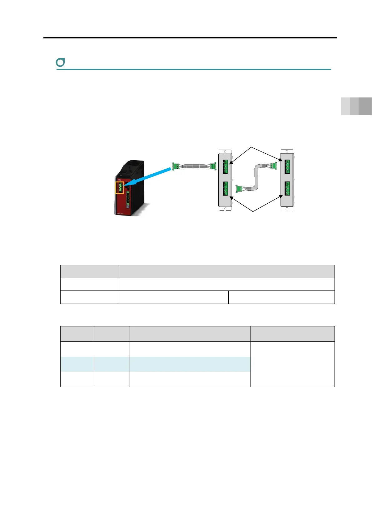
Connect regenerative resistor unit (s) with attached cables as shown in the figure below.
1) When connecting 1 unit : Connect RESU(D)-1 with the enclosed cable (CB-ST-REU)
2) When connecting 2 or more units : Connect RESU(D)-1 with the enclosed cable (CB-ST-REU)
● Wiring Image
● Specifications of external regenerative resistor connector
Item Items and Model
Connector name External regenerative resistor connector (RB)
Model Controller side: GIC2.5/3-GF-7.62 Cable side: GIF2.5/3-STF-7.62
● Pin assignment
Pin No.
Signal
Name
Items Applicable cable diameter
1 RB+
Regeneration resistor+
(Motor drive DC voltage)
Dedicated cable is
enclosed to regenerative
resistor unit
2 RB- Regeneration resistor-
3 PE Ground terminal
RB IN
200 V power supply unit
External regenerative resistor
connector
1)
1)
RESU-1
RESUD-1
RESU-1
RESUD-1
RB OUT
 Loading...