3.1 System configuration
3-1
3. Wiring
PLC
Accessories
Accessories
Accessories
Accessories
Option
Option Option
Option
Option
Option
Motor drive
DC power supply PSA-200
<Model: PSA-200-□>
It generates power of drive
200 V.
* Six axis at the maximum of
ELECYLINDER can be
connected in the maximum
connectable motor wattage.
Motor power supply cable
<Model: CB-EC-PW□□□-RB>
It is a cable to supply the
drive 200 V power to an
actuator.
Power / I/O connector
Connector for connecting customer-side
power wiring.
<Model: 1-1871940-6>
<Wires>
For “24 V” and “0 V” , the thickness should be AWG18.
For others, it should be AWG26 or higher.
* All cables should be 10 m or shoter.
Power / I/O cable
<Model: CB-EC-PWBIO□□□-RB>
Cable for connecting power and
PLC I/O signals.
24 V DC
power supply
<Model: PSA-24>
EC connection unit
<Model: REC-GW-□
+ RCON-EC-4>
It is a unit to connect to
field network.
Power supply / communication cable
<Model: CB-EC-REC□□□-RB>
Cable for connecting actuator and
EC connection unit.
Touch Panel
Teaching Pendant
<Model: TB-03-□>
Touch Panel
Teaching Pendant
<Model: TB-02-□>
PC software
Only software
<Model: IA-OS>
Equipped with dedicated
connection cable
<Model: IA-OS-C>
Dedicated connection cable
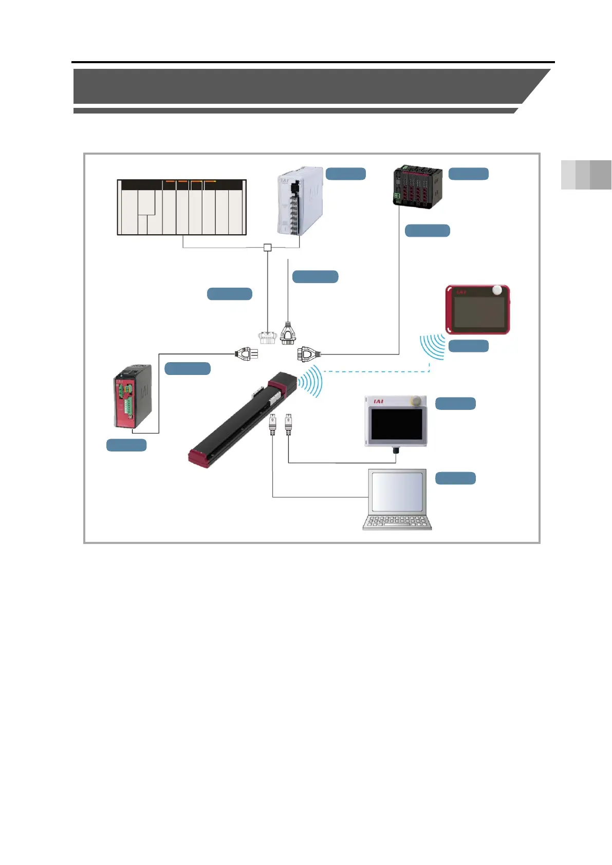
3.1 System configuration
The following shows the system configuration.
By supplying 24 V DC to ELECYLINDER and 200 V AC (or 100 V AC) to the drive 200 V power
supply, ELECYLINDER can be operated with signals from the host device input to
ELECYLINDER.
This manual introduces an example using a PLC connected as the master device.
 Loading...