Home
IAI
Industrial Equipment
ELECYLINDER EC-S13
IAI ELECYLINDER EC-S13 User Manual
4
of 1
of 1 rating
258 pages
Give review
Manual
Specs
To Next Page
To Next Page
To Previous Page
To Previous Page
Loading...
8.6 How to replace components
8-33
8. Maintenance and Inspection
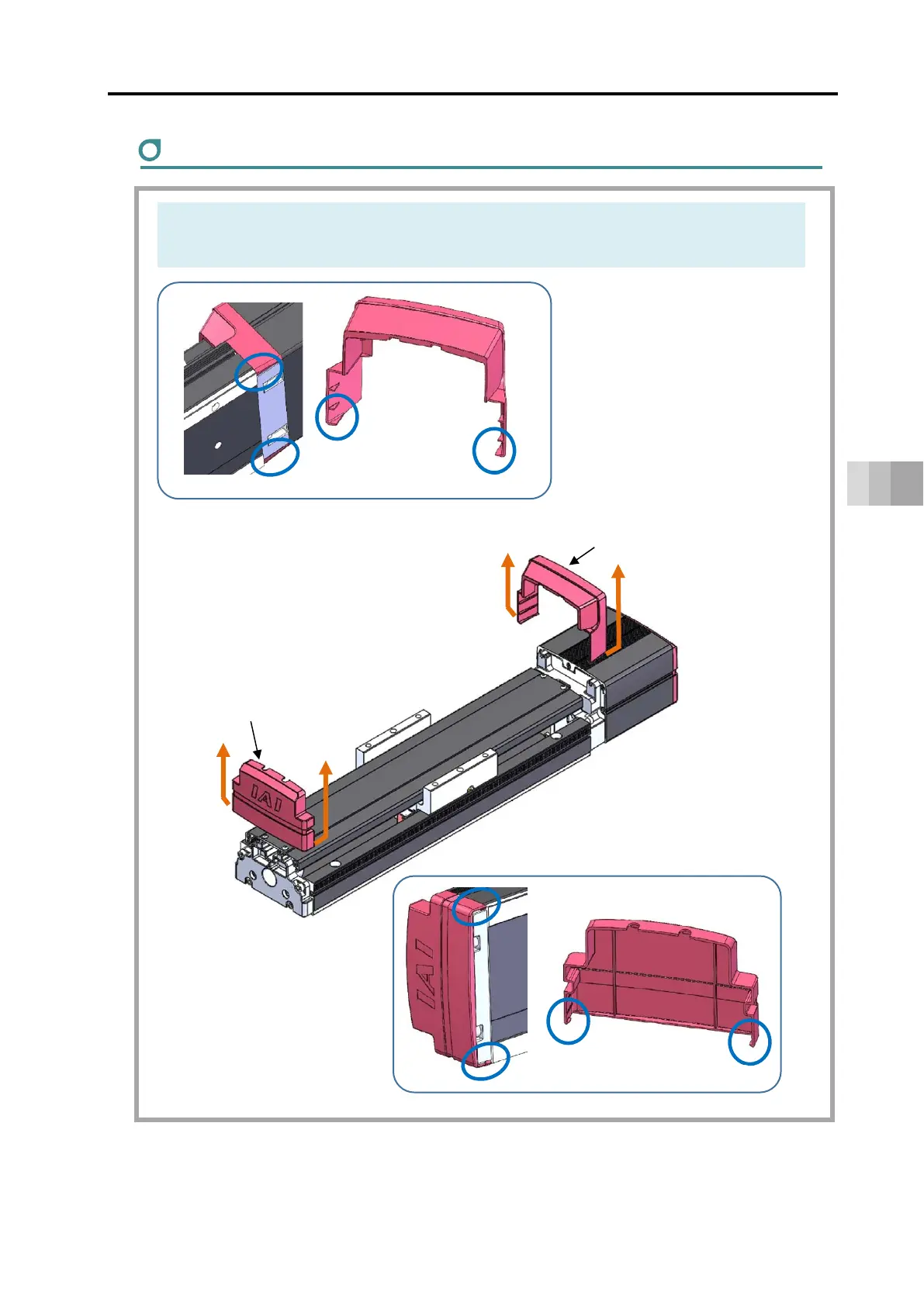
Replacement of intermediate support cushion
1)
In order to take off the front bracket cover and rear bracke
t cover, open them up to
the outer side and pull them up.
Front bracket cover
Rear bracket cover
Hooks on base seating surface
218
220
Table of Contents
Default Chapter
5
Table of Contents
5
Safety Guide
11
Precautions for Handling
19
International Standard Compliance
21
Precautions for Handling Wireless Operation
22
Precautions for Axis Operation with Wireless Connection
25
Part Names
26
Chapter 1 Specifications
33
Checking the Product
33
Components
33
How to Read the Model Nameplate: ELECYLINDER
35
Checking the Product
35
How to Read the Model Nameplate: Motor Drive DC Power Supply PSA-200
36
Motor Drive DC Power Supply PSA-200
36
How to Read the Model Number
37
Product List
38
Mechanical Specifications
39
Slider Type
39
Duty Ratio
57
Options
59
RCON-EC Connection Specification (Model: ACR)
59
With Brake (Model: B)
59
Indicated Grease Applied Type (Model: G5)
59
Home Reverse Specification (Model: NM)
59
PNP Specification (Model: PN)
59
Wireless Communication Specification (Model: WL)
59
Wireless Axis Operation Specification (Model: WL2)
60
Two-Circuit Power Supply Specification (Model: TMD2)
60
Regenerative Resistor Unit (Option)
61
Specifications of Regenerative Resistor Unit
61
Accessories
62
Power I/O Cable
62
Power I/O Connector
63
Motor Power Supply Cable
64
Chapter 2 Installation
65
Precautions for Transportation
67
Installation and Storage/Preservation Environment
68
Installation Environment
68
Storage/Preservation Environment
69
Installation of Slider Type
70
Installation Surface
70
Mounting Orientation Type: S13/S13X/S15/S15X
71
Fixing Bolt
73
Body Mounting
74
Mounting Transported Objects
75
How to Install Motor Drive DC Power Supply PSA-200
76
How to Install, Orientation of Installation
76
Chapter 3 Wiring
77
System Configuration
79
Electrical Specifications
80
Specifications Table
80
Max. Units Connectable to Motor Drive DC Power Supply PSA-200
84
Current Amperage and Heat Generation of Motor Drive DC Power Supply PSA-200
85
Selection of Circuit Breaker
86
Selection of Leak Current Breaker
86
I/O Specifications of Actuator Main Unit
87
Status Output Connector for Motor Drive DC Power Supply PSA-200
88
Number of Connectable Regenerative Resistor Units (Option) (Reference)
89
Brake Release Method (for Brake-Equipped Type)
90
Grounding Terminal Actuator Main Unit
90
Grounding Terminal Motor Drive DC Power Supply PSA-200
91
Connection Arrangement Diagram
92
Motor Drive DC Power Supply PSA-200
92
Actuator Main Unit
94
Example for Wiring Actuator Units and Motor Drive DC Power Supply PSA-200
97
Wiring Connections (for Connectors)
101
Connectivity between Actuator Units and Motor Drive DC Power Supply
101
Power Supply Connector
101
Motor Drive DC Power Supply
101
Regenerative Resistor Unit (Option)
103
DC Power Supply Wiring
105
PLC Wiring
107
Connector Wiring Method
108
Brake Release Wiring
110
Wiring Connections (for Cables)
110
Power I/O Cable
110
Power I/O Cable Connection
111
DC Power Supply Wiring
112
PLC Wiring
114
Brake Release Wiring
115
Chapter 4 Operation
117
Basic Operation
119
Order to Turn Power on
120
Order to Turn Power off
120
Teaching Tool Connections and Testing Operation
121
Teaching Pendant Connection
121
ELECYLINDER Test Operation
122
Stop Position/Operating Conditions (AVD) Setting/Adjustment
123
Stop Position Setting/Adjustment (Forward End / Backward End)
124
Operating Conditions (AVD) Setting/Adjustment
125
I/O Signals
128
I/O Signal List
128
[ST0] [ST1] Signals: Movement Command Input (Backward/Forward)
129
[RES] Signal: Alarm Clear Input
130
[BKRLS] Input: Brake Release Input
130
[LS0] [LS1] Signals: Position Detection Output (Backward End / Forward End)
131
[*ALM] Signal: Alarm Output
132
Signal Input Time Constant
132
Operating Method from Master Device
133
Positioning Operation: [ST0] [LS0] [ST1] [LS1] Signals
133
Preventive/Predictive Maintenance
139
Chapter 5 Preventive/Predictive Maintenance
140
Maintenance Information
140
Total Travel Count
140
Total Travel Distance
140
Overload Warning Level
141
Capacitor Assumed Life Exceeded Warning
142
Setting Maintenance Information
143
Switching to Maintenance Information Window
143
Basic Operation
144
Chapter 6 Parameters
147
Precautions Regarding Parameters
147
How to Change Parameters
148
Edit Parameters Window
148
Basic Operation
149
Parameter List
151
Parameter Function Descriptions
152
Parameter No.1: Operation Range Adjustment
152
Parameter No.2: Auto Switch "LS" Signal Detection Range Adjustment
153
Parameter No.3: Change Home Return Direction
154
Parameter No.4: Home Position Adjustment
155
Parameter No.5: Smooth Accel/Decel Setting
156
Parameter No.7: Wireless Function Setting
157
Chapter 7 Troubleshooting
161
Troubleshooting Confirmations
161
Troubleshooting Diagnosis
166
Troubleshooting with no Alarm Generated
168
Operation Failure
168
Abnormal or Unstable Operation
170
Troubleshooting by Alarm Groups
173
Alarm Group A: Overload Alarm
174
Alarm Group B: Motor Abnormality Alarm
175
Alarm Group C: Controller Abnormality Alarm
176
Alarm Group D: Controller-Encoder Abnormality Alarm
177
Alarm Group E: Supply Voltage / Power Capacity Abnormality Alarm
178
Alarm in Motor Drive DC Power Supply PSA-200
179
Warning: Maintenance Warning 1
180
Warning: Maintenance Warning 2
180
Warning: Maintenance Warning 3
181
Warning: Maintenance Warning 4
182
Warnings in Motor Drive DC Power Supply PSA-200
183
Chapter 8 Maintenance and Inspection
187
Precautions for Maintenance and Inspection Work
187
Inspection Items and Schedule
189
Slider Type (EC-S13/S13X/S15/S15X)
189
Grease Supply Timing (Guideline)
189
Visual Inspection Items
190
External Visual Inspection
190
Internal Visual Inspection
191
Cleaning
195
External Cleaning
195
Internal Cleaning
195
Greasing Method
196
How to Replace Components
204
Controller Replacement (Motor Cover Assembly Replacement)
204
Wireless Communication Circuit Board Replacement
209
Motor Unit Replacement
210
Replacement of Intermediate Support Cushion
219
Fan Replacement of Motor Drive DC Power Supply PSA-200
228
Chapter 9 External Dimensions
233
Slider Type External Dimensions
233
Ec-S13
233
Ec-S13X
234
Ec-S15
235
Ec-S15X
236
Motor Drive DC Power Supply PSA-200
237
Chapter 10 Life
241
Concept of Life for Slider Type
241
How to Calculate Operation Life
241
Relation between Operation Life and Moment
243
Concept of Life for Controller
243
How to Take Concept of Product Life for Motor Drive DC Power Supply PSA-200
243
Chapter 11 Warranty
247
Warranty Period
247
Scope of the Warranty
247
Honoring the Warranty
247
Limited Liability
248
Conformance with Applicable Standards/Regulations, Etc
248
And Application Conditions
248
Other Items Excluded from Warranty
248
4
Based on 1 rating
Ask a question
Give review
Questions and Answers:
Need help?
Do you have a question about the IAI ELECYLINDER EC-S13 and is the answer not in the manual?
Ask a question
IAI ELECYLINDER EC-S13 Specifications
General
Brand
IAI
Model
ELECYLINDER EC-S13
Category
Industrial Equipment
Language
English