9.1 Slider type
9-1
9. External Dimensions
*1 The battery charge status display LED turned on shows that power is charged inside the controller. Make sure to turn the power off
and confirm the LED is turned off before having a wiring work or inspection work in order to prevent electric shock.
(Note) After the home-return operation gets conducted, the slider should move to the mechanical end. Pay attention to interference to peripherals.
Base datum surface
1.5
T-shaped slot: M4 (Both Sides)
V
20
J
109
50 50C D×200P
50
K
130
E-φ9 Thru,
φ14 Counterbore dept. 8.5
(from opposite side)
132
B
2-φ8 H7 Reamed, depth 10
(from base seat surface)
Oblong
hole
Z
Z
Q
A
L
ST52.5
5
5
Must be 100 or more
106
120
90
120 (Reamed hole tolerance±0.02)
129.5 (W/o brake)
147.5 (With brake)
31.5
44.5
104.5
134
4-M8 Depth 20
2-φ8 H7 Reamed, depth 10
M.E.
S.E.M.E.
Caution for interferrence to
workpiece attached to slider
HOME
32 58
132
130
90
(Upper surface of slider)
(134)
96.7 (Total Height)
14 14
Allowable moment
offset datum position
Da tum surfa ce
(Dimension B range)
125
1
69
68.4
68.5
26.5
28.4
46
M4 (For grounding connection)
Teaching port
Power I/O connector
Motor power connector
Connector Guard Attachment (M3)
Status LED
Battery charge status display LED *1
10
J
(
R
)
8
+0.015
0
From base seat surface depth 10
Detailed view of Q
Details of base oblong hole
φ
1
2
O
p
e
n
i
n
g
Detailed view of V
Greasing port
φ6
Fitting diameter
Grease fitting for
ball screw/guide
(Same on opposite side)
φ14
φ9
50
8.5
32
Cross section of Z-Z
Detail of counterbore for base installation
P
(32)
1.8
4.3
7.3
4.3
Detailed view of P
Details of T-shaped slot
(Dimension B range)
Base seat surface
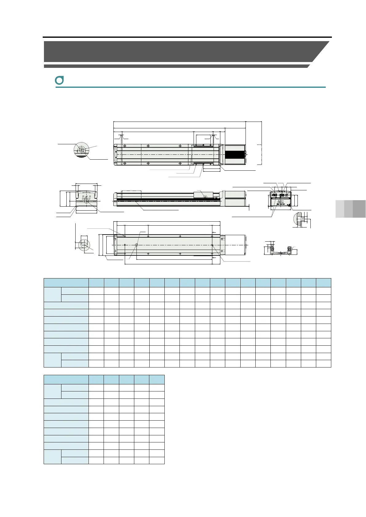
9.1 Slider type external dimensions
EC-S13
M.E.: Mechanical end, S.E.: Stroke end, ST: Stroke
■ Dimensions and Mass by Stroke
Stroke 100 150 200 250 300 350 400 450 500 550 600 650 700 750 800 850
L
W/o Brake 478 528 578 628 678 728 778 828 878 928 978 1028 1078 1128 1178 1228
With Brake 496 546 596 646 696 746 796 846 896 946 996 1046 1096 1146 1196 1246
A 348.5 398.5 448.5 498.5 548.5 598.5 648.5 698.5 748.5 798.5 848.5 898.5 948.5 998.5 1048.5 1098.5
B 297 347 397 447 497 547 597 647 697 747 797 847 897 947 997 1047
C 197 247 297 147 297 247 297 147 197 247 297 147 197 247 297 147
D 0 0 0 1 1 1 1 2 2 2 2 3 3 3 3 4
E 4 4 4 6 6 6 6 8 8 8 8 10 10 10 10 12
J 98.5 123.5 148.5 273.5 298.5 323.5 348.5 473.5 498.5 523.5 548.5 673.5 698.5 723.5 748.5 873.5
K 197 247 297 347 397 447 497 547 597 647 697 747 797 847 897 947
Mass
(kg)
W/o Brake 7.3 7.8 8.3 8.7 9.2 9.7 10.2 10.7 11.1 11.6 12.1 12.6 13.1 13.6 14.0 14.5
With Brake 7.8 8.3 8.8 9.3 9.8 10.3 10.7 11.2 11.7 12.2 12.7 13.1 13.6 14.1 14.6 15.1
Stroke 900 950 1000 1050 1100
L
W/o Brake 1278 1328 1378 1428 1478
With Brake 1296 1346 1396 1446 1496
A 1148.5 1198.5 1248.5 1298.5 1348.5
B 1097 1147 1197 1247 1297
C 197 247 297 147 197
D 4 4 4 5 5
E 12 12 12 14 14
J 898.5 923.5 948.5 1073.5 1098.5
K 997 1047 1097 1147 1197
Mass
(kg)
W/o Brake 15.0 15.5 16.0 16.4 16.9
With Brake 15.5 16.0 16.5 17.0 17.5
(Unit: mm)
 Loading...