3.5 Wiring connections (for cables)
3-35
3. Wiring
Two-circuit power supply specification TMD2 (Option)
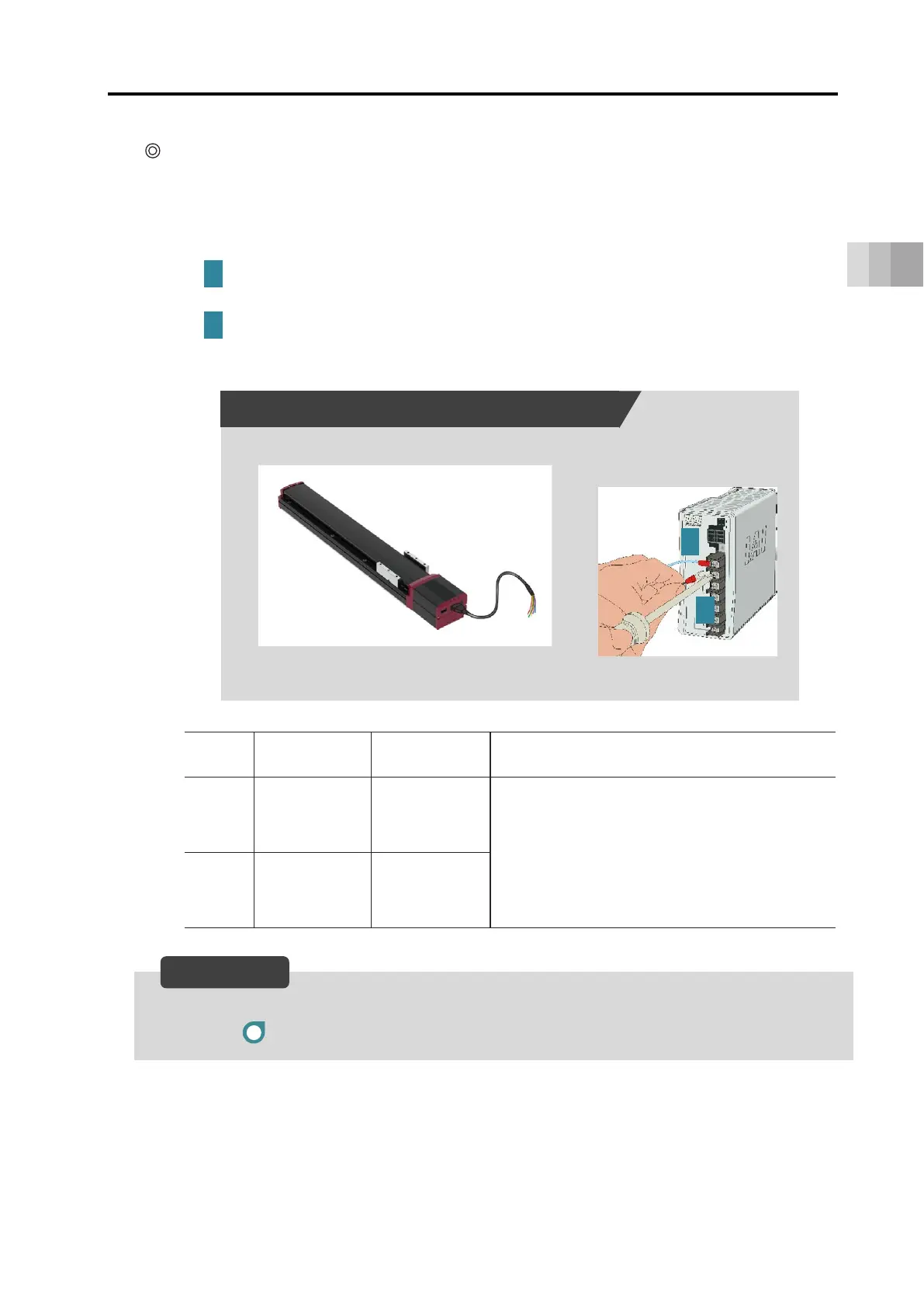
Connect the power wiring to the power I/O cable.
Connect the 24 V DC power supply to the terminal block after terminal-processing the 24 V
(control) and 0 V wires of the power I/O cable.
Connect the 24 V (control) wire (insulation color: light blue) to the +24 V terminal of
the 24 V DC power supply.
Connect the 0 V wire (insulation color: black) to the 0 V terminal of the 24 V DC
power supply.
Wiring
color
Signal
abbreviation
Function
overview
Required specifications
Light
blue
24 V
(Control)
Control power
supply input
Control power voltage: 24 V DC ±10%
Control power capacity: 0.32 A
Brake power supply: 0.875 A
(when in overexcitation)
(Option)
When teaching pendant used:0.15 A
Black 0 V Ground
By cutting off the 24V (drive source) (insulation color: red), it turns to the stop condition.
→ Refer to Example for wiring actuator units and motor drive DC power supply PSA-200.
2
1
24 V DC power supply connection diagram
24 V DC power supply
ELECYLINDER / Power I/O cable
1
2
Reference
 Loading...