3.3 Connection arrangement diagram
3-18
3. Wiring
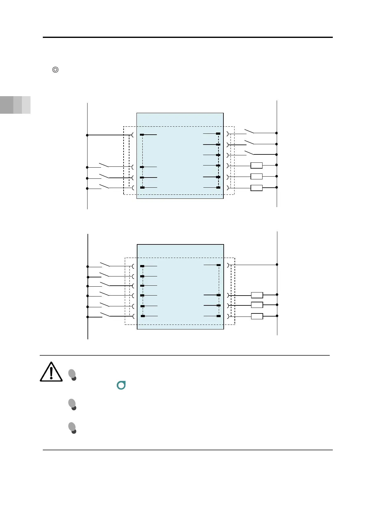
[For PNP specification]
[For NPN specification]
Note 1
B1
B3
B5
B2
B4
A3
A4
A5
24 V
BKRLS
ST0
ST1
RES
* ALM
LS0
LS1
0 V
24 V DC
Brake release
4 V power supply
(driving source)
Alarm clear
Backward complet
Forward complete
Alarm
A1
0V
Ground
Backward
Forward
ELECYLINDER (PNP specification)
Power I/O connector
A2
24 V
4 V power supply
(control)
Note 1
ELECYLINDER (NPN specification)
Backward complet
Power I/O connector
A1
B3
B5
B4
A3
A4
A5
0 V
ST0
ST1
RES
* ALM
LS0
LS1
0 V
24 V DC
Ground
Alarm clear
Forward complete
Alarm
B1
24 V
24 V power supply
(driving source)
Backward
Forward
B2
24 V power supply
(control)
24 V
A2
Brake release
BKRLS
Here the wiring connection method with a power I/O connector is introduced.
Two-circuit power supply specification TMD2 (Option)
Caution
It should fall into the stop condition by cutting off the 24 V (drive source) signals.
→ Refer to Example for wiring actuator units and motor drive DC power supply
PSA-200.
[Note 1] This switch releases the brake forcibly for actuators equipped with a brake.
The switch power capacity requires 24 V DC ±10% and 200 mA or more.
[*ALM] is a b-contact (active-low) signal.
The output signal is ON in normal conditions and OFF when an alarm occurs.
 Loading...