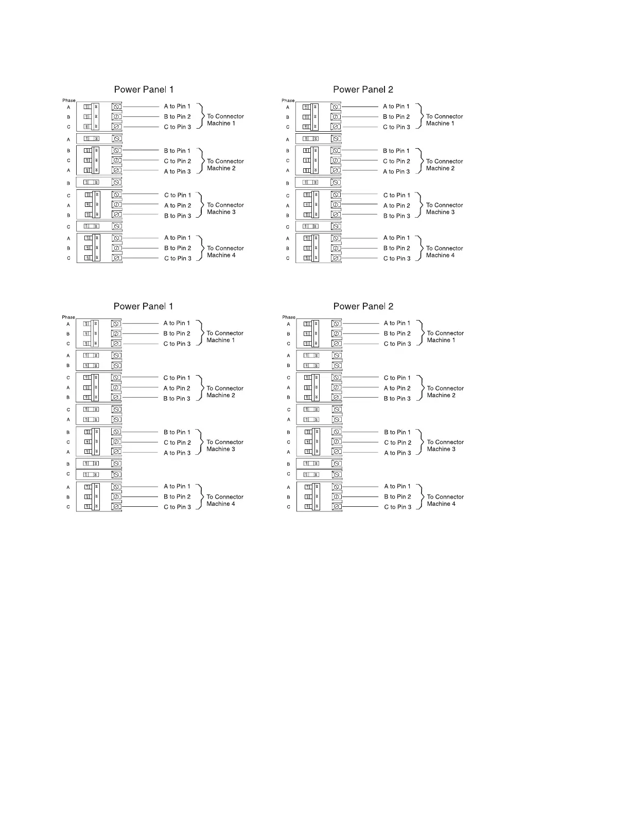
alternated with single-pole breakers, so that the three-pole breakers do not all begin on Phase A.
The following figure shows another way of distributing the unbalanced load evenly. In this case, the
three-pole breakers are alternated with two-pole breakers.
Power Cord Configuration
The power cords exit the system from different points of the frame as indicated in the following illustration.
For raised-floor applications, we recommend that both cords be routed to the rear of the frame and
through the same floor-tile cutout. For more information about raised-floor applications, refer to “Cutting
90 Site and Hardware Planning Information
 Loading...