and Placement of Floor Panels” on page 105 and the raised-floor diagram on page 106.
A
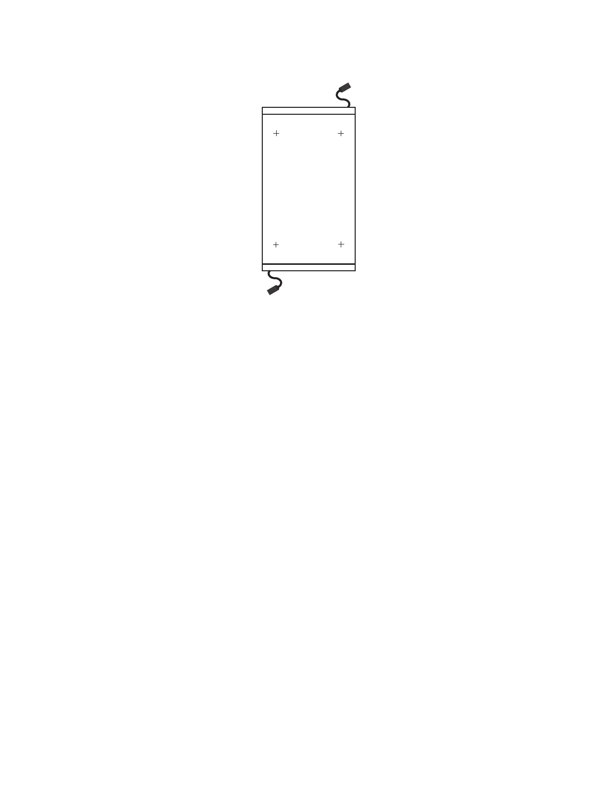
System
(Top Down View)
Front
Rear
Checking the Facility Outlets and Power Source
CAUTION:
Do not touch the receptacle or the receptacle faceplate with anything other than your test probes
before you have met the requirements in “Checking the Facility Outlets and Power Source” below.
Performing the following will ensure that appropriate power will be used by the Eserver pSeries 655. The
following checklist is for reference purposes, and will likely be performed by a service engineer prior to
installation.
__ 1. The Eserver pSeries 655 is equipped to use 200-240V / 380-415V / 480V ac, three-phase.
Check that the correct power source is available.
__ 2. Before system installation, locate and turn off the branch circuit CB (circuit breaker). Attach tag
S229-0237, which reads “Do Not Operate.”
Note: All measurements are made with the receptacle faceplate in the normally installed position.
__ 3. Some receptacles are enclosed in metal housings. On receptacles of this type, perform the
following steps:
a. Check for less than 1 volt from the receptacle case to any grounded metal structure in the
building, such as a raised-floor metal structure, water pipe, building steel, or similar structure.
b. Check for less than 1 volt from receptacle ground pin to a grounded point in the building.
Note: If the receptacle case or faceplate is painted, be sure the probe tip penetrates the paint and
makes good electrical contact with the metal.
__ 4. Check the resistance from the ground pin of the receptacle to the receptacle case. Check
resistance from the ground pin to building ground. The reading should be less than 1.0 ohm, which
indicates the presence of a continuous grounding conductor.
__ 5. If any of the checks made in steps 3 and 4 are not correct, remove the power from the branch
circuit and make the wiring corrections; then check the receptacle again.
Note: Do not use the digital multimeter to measure grounding resistance.
__ 6. Check for infinite resistance between the phase pins. This is a check for a wiring short.
Chapter 2. Physical Characteristics of Systems 91
 Loading...