Installing and removing a drive in bay 1 99
Installing and removing a drive in bay 1 (continued)
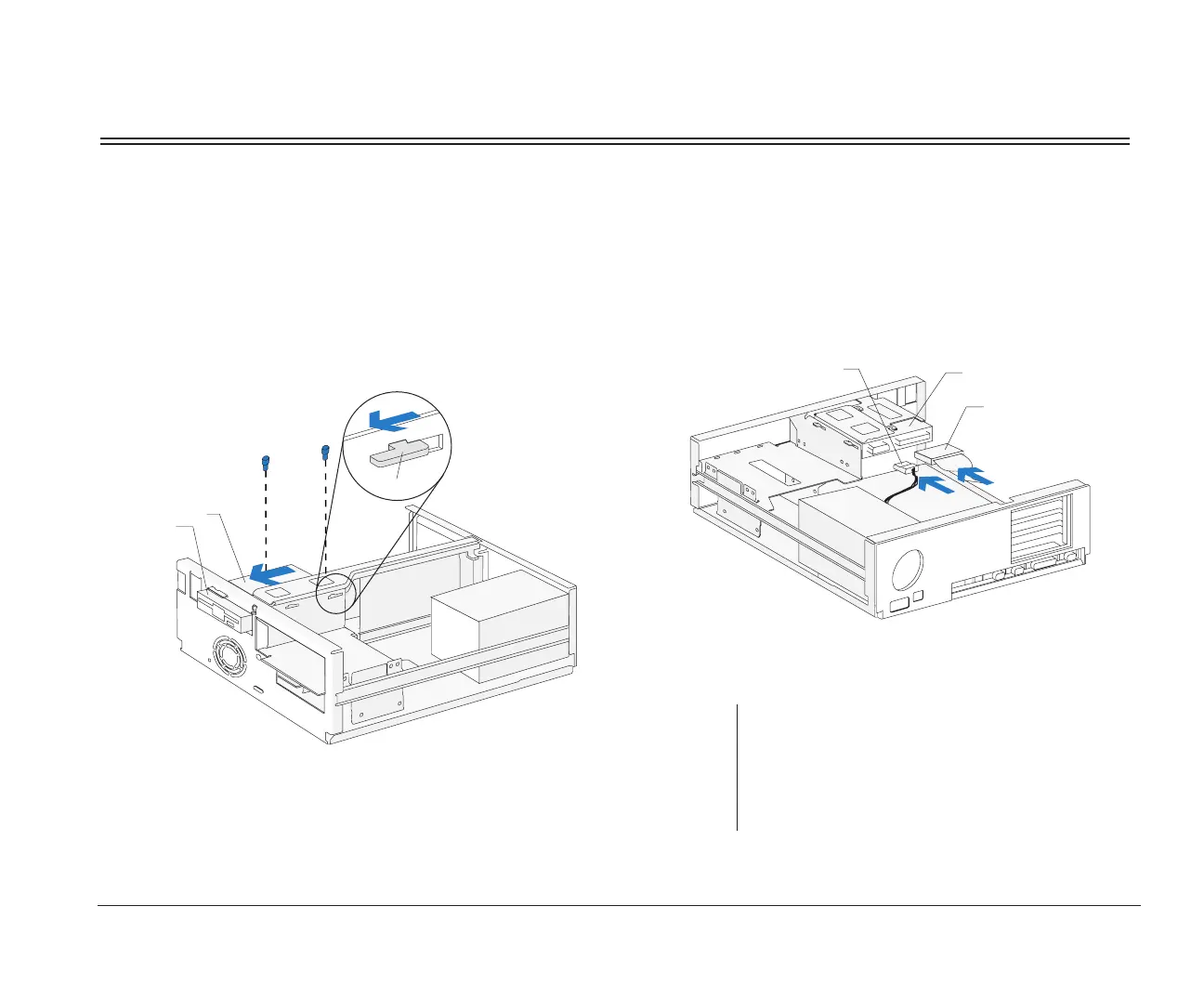
3. Left bracket replacement
Insert the left bracket catches into the slots and
slide the bracket forward until it locks into place.
Align the screw holes and insert the screws
Front View
Left Bracket
Catch
Drive
4. Drive cable connection
Connect all drive cables.
note:
If you are adding a diskette or tape drive that attaches
to the Diskette connector, make sure the signal cable
you plug into the drive is attached to the Diskette
connector on the system board. To identify the
Diskette connector, see “Identifying parts of the
system board” on page 127.
(Back View)
Drive
Power Cable
Signal Cable
bi2gntce.bk : bi2gusys.doc Page 99 Saturday, June 3, 1995 6:54 AM

 Loading...


