98 Installing and removing a drive in bay 1
Installing and removing a drive in bay 1
Bay 1 holds a 3.5-inch slim drive, such as a diskette or tape drive.
Before beginning these steps, you may need to remove any installed adapter cards. For instructions on removing
adapter cards, see page 92.
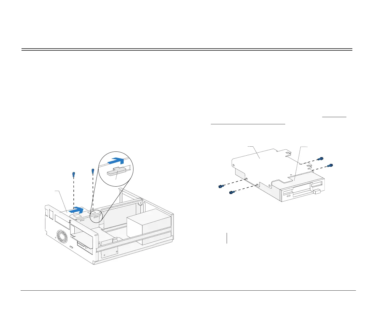
1. Left bracket removal
Remove the screws and disconnect any drive
cables. (Notice how the cables are attached. You
may need to attach these cables when you are
finished.) Slide the left bracket back to release the
catches, and then remove the bracket (with any
attached drive, if present).
.
(Front View)
Left Bracket
Catch
2. Drive attachment/removal
For drive attachment, lay the drive upright on a flat
surface. Place the bracket on top of the drive. Align
the screw holes and insert the screws. (Reverse
this step for drive removal.)
note: Screw locations may differ.
(Front View)
Drive
Left
Bracket
bi2gntce.bk : bi2gusys.doc Page 98 Saturday, June 3, 1995 6:54 AM

 Loading...


