120 Installing and removing a drive in bay 2 or 3
Installing and removing a drive in bay 2 or 3
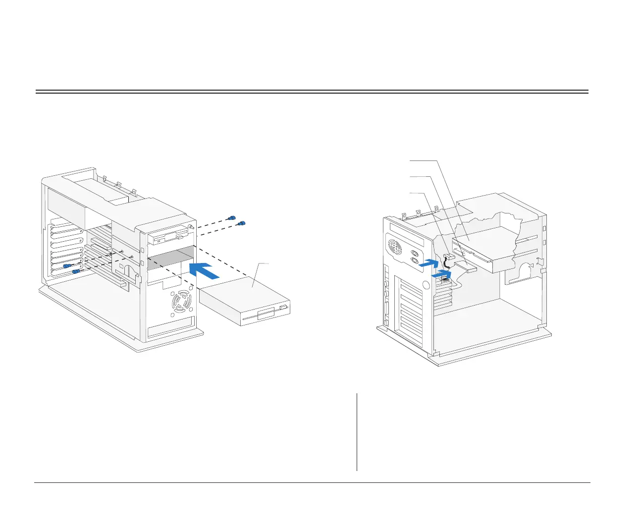
Bay 2 or 3 can hold up to a 5.25-inch half high drive, such as a diskette, tape, or CD-ROM drive. For drive removal,
reverse these steps.
1. Insert the drive into the bay. Align the screw holes
and insert the four screws.
Front View
Drive
2. Connect the power and signal cables to the drive.
note:
If you are adding a diskette drive or tape drive that attaches
to the diskette connector, make sure the signal cable you
plug into the drive is attached to the Diskette connector on
the system board. If you are adding a CD-ROM, it is recom-
mended that you use the signal cable attached to the Local
Bus connector on the system board. To identify the con-
nectors on the system board, see page 127.
Drive
Signal Cable
Power Cable
(Back View)
bi2gntce.bk : bi2gusy2.doc Page 120 Saturday, June 3, 1995 6:54 AM

 Loading...


