104 Installing and removing a hard disk in bay 4
Installing and removing a hard disk in bay 4
Bay 4 holds a 3.5-inch slim hard disk.
Before beginning these steps, you must
remove any drives installed in bays 1 and 2. For instructions on removing a
drive from bay 1, see page 98. For instructions on removing a drive from bay 2, see page 100.
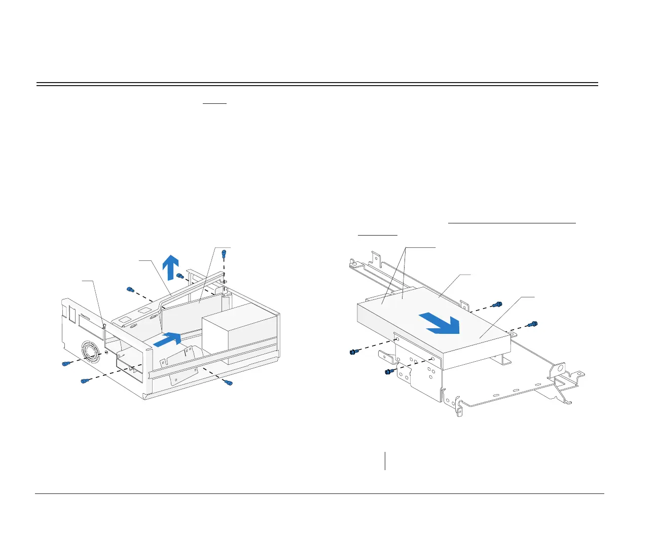
1. Right bracket removal
Remove the screws and disconnect any drive
cables. (Notice how the cables are attached. You
may need to attach these cables when you are
finished.) Slide the right bracket back to release the
catch, then lift and remove the bracket.
.
Right Bracket
Catch
Riser Card
Front View
2. Drive attachment/removal
For drive attachment, turn the bracket upside down
and slide the drive into the bracket with the
component side down. Align the screw holes on
the drive with the screw holes on the bracket.
Insert the screws. (Reverse this step for drive
removal.)
note: Screw locations may differ.
Hard Disk
Connectors
Hard Disk
Right Bracket
Front Upside Down View
bi2gntce.bk : bi2gusys.doc Page 104 Saturday, June 3, 1995 6:54 AM

 Loading...


