Installing and removing a hard disk in bay 3 103
Installing and removing a hard disk in bay 3 (continued)
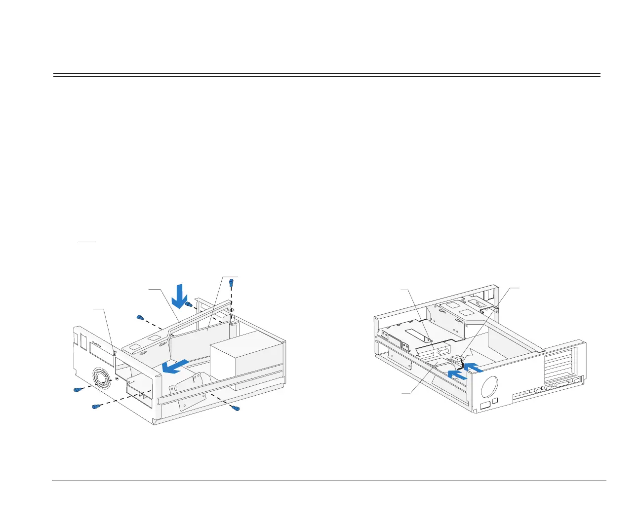
3. Right bracket replacement
Slide the right bracket into the bay. Make sure you
insert the catch into its slot on the front of the
system unit. Also make sure the riser card is
located to the left of the bracket.
Align the screw holes. Insert the two front screws
first
, then insert the remaining screws. (The riser
card should be located to the left of the bracket so
that the screws go through the riser card first.)
Right Bracket
Catch
Riser Card
Front View
4. Hard disk cable connections
Connect all drive cables. Reinstall any drives you
removed in bays 1 and 2. For instructions on
installing a drive in bay 1, see page 98. For
instructions on installing a drive in bay 2, see
page 100.
(Back View)
Signal Cable
Power Cable
Drive
bi2gntce.bk : bi2gusys.doc Page 103 Saturday, June 3, 1995 6:54 AM

 Loading...


