Installing and removing a drive in bay 2 101
Installing and removing a drive in bay 2 (continued)
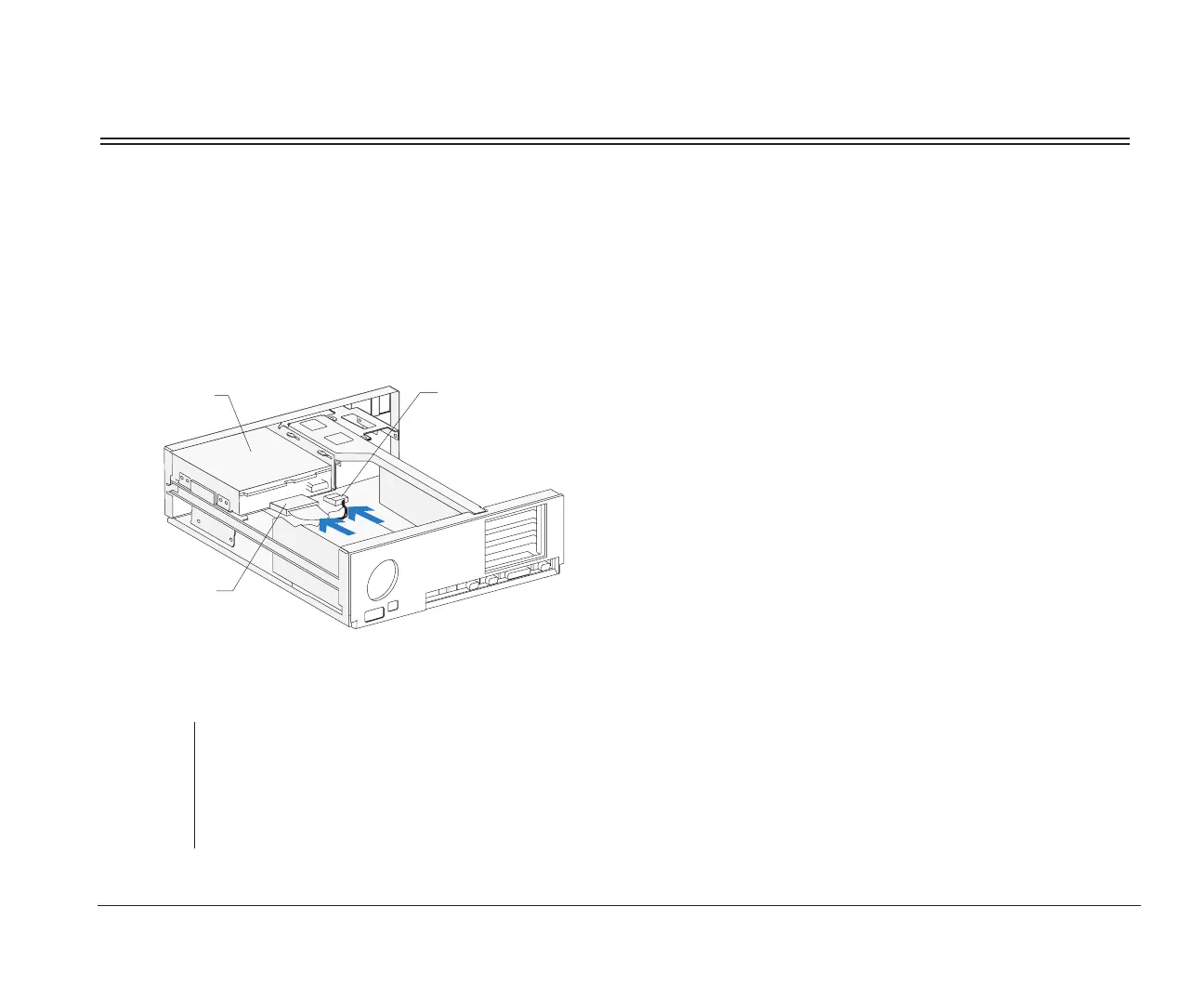
3. Drive cable connections
Connect all drive cables.
note:
If you are adding a diskette, tape, or CD-ROM drive
that attaches to the Diskette connector, make sure the
signal cable you plug into the drive is attached to the
Diskette connector on the system board. To identify
the Diskette connector, see “Identifying parts of the
system board” on page 127.
(Back View)
Signal Cable
Power Cable
Drive
4. Left bracket replacement and drive cable
connections
For instructions on replacing the left bracket and
connecting the drive cables for any drive that may
be attached to the left bracket, see page 99.
bi2gntce.bk : bi2gusys.doc Page 101 Saturday, June 3, 1995 6:54 AM

 Loading...


