Getting started with IDEC SmartRelay
8
IDEC SmartRelay Manual
Versions
The following IDEC SmartRelay versions are available:
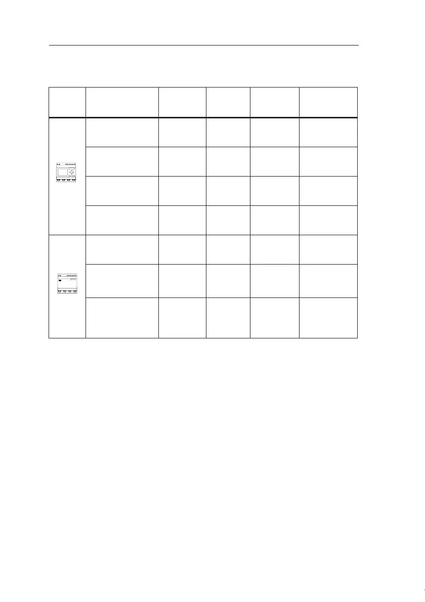
Symbol Description Supply
Voltage
Inputs Outputs Properties
FL1C-H12RCE 12/24 V DC
8 digital
(1)
(1): Of those can be used alternatively: 2 analog inputs (0 ... 10V) and 2 fast inputs.
4 relays
(10 A)
FL1C-H12SND 24 V DC
8 digital
(1)
4 Transistor
24V / 0.3A
no clock
FL1C-H12RCA
(2)
(2): The digital inputs can be operated with P or N action.
24 V AC/
24 V DC
8 digital 4 relays
(10A)
FL1C-H12RCC
(3)
(3): Two groups consisting of 4 inputs each. Each group must be connected to the
same phase. It is possible to interconnect groups with a different phase.
100...240 V
AC/DC
8 digital 4 relays
(10A)
FL1C-B12RCE 12/24 V DC
8 digital
(1)
4 relays
(10A)
no display unit
no keyboard
FL1C-B12RCA
(2)
24 V AC /
24 V DC
8 digital 4 relays
(10A)
no display unit
no keyboard
FL1C-B12RCC
(3)
100...240 V
AC/DC
8 digital 4 relays
(10A)
no display unit
no keyboard
Courtesy of Steven Engineering, Inc. ● 230 Ryan Way, South San Francisco, CA 94080-6370 ● General Inquiries: (800) 670-4183 ● www.stevenengineering.com
 Loading...
