IDEC SmartRelay installation and wiring
IDEC SmartRelay Manual 27
Note
The FL1B-J2B2 expansion module provides further analog inputs.
Always use twisted and shielded cables for analog signals, and
keep these as short as possible.
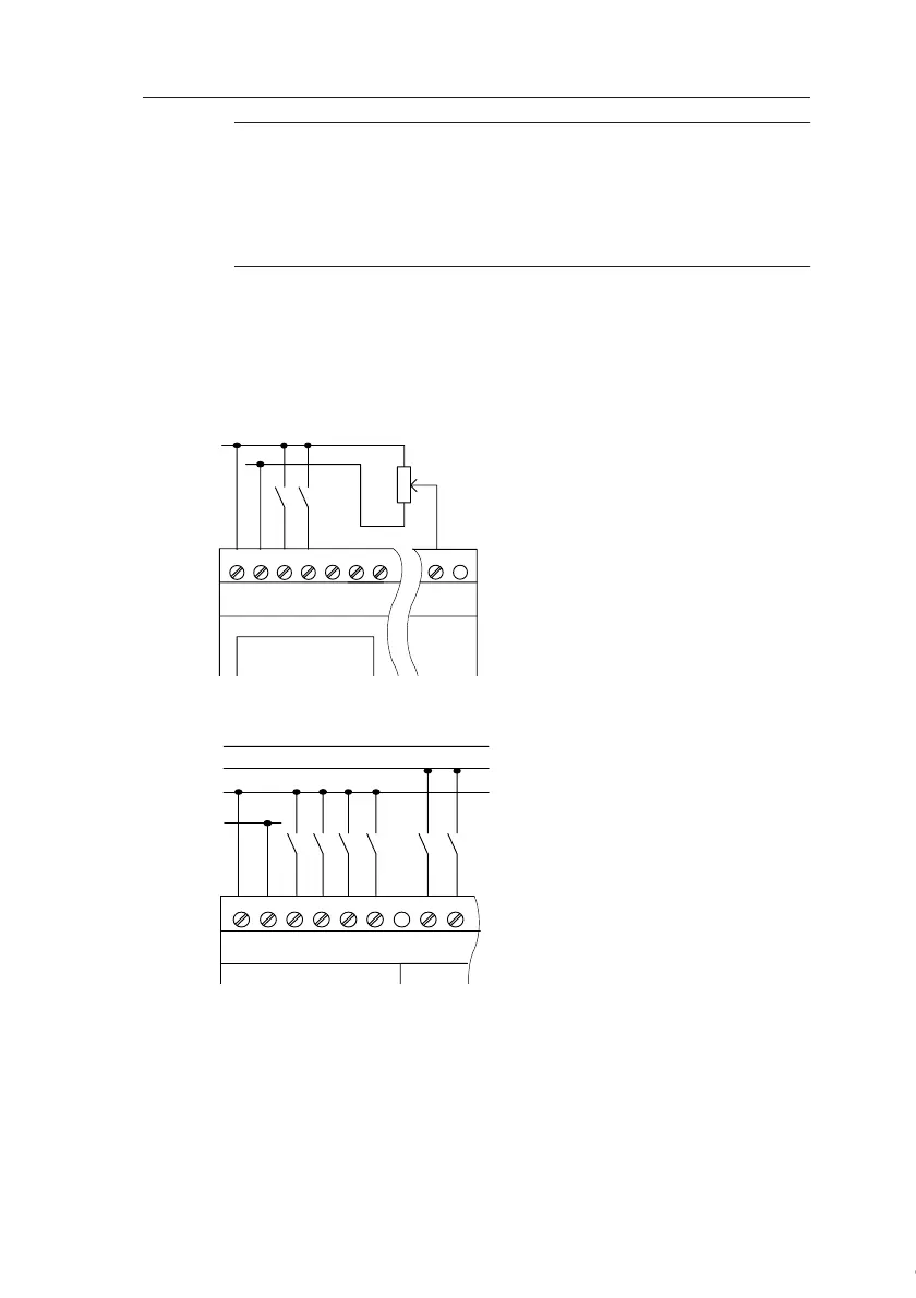
Sensor connections
To connect sensors to the IDEC SmartRelay :
FL1C-H12RCA / FL1C-B12RCA / FL1C-H12RCE /
FL1C-B12RCE/ FL1C-H12SND
FL1C-H12RCC / FL1C-B12RCC
L+
M
ML+ I1 I2 I3 I4 I5 I8
The inputs of these devices not isolated
and therefore require a common reference
potential (chassis ground ).
At the FL1C-H12RCE/FL1C-B12RCE and
FL1C-H12SND modules, you can tap ana-
log signals between the supply voltage and
chassis ground.
L1
N
L3
L2
NL1 I1 I2 I3 I4 I5 I6
The inputs of these devices are arranged in
2 groups, each consisting of 4 inputs. Differ-
ent phases are only possible between
blocks, but not within the blocks.
Courtesy of Steven Engineering, Inc. ● 230 Ryan Way, South San Francisco, CA 94080-6370 ● General Inquiries: (800) 670-4183 ● www.stevenengineering.com
 Loading...
