EN
4 - HANDLING AND INSTALLATION BOSS 332/545/552 HD
4 - Pag. 8 / 32
4.4.3 Preliminary positioning
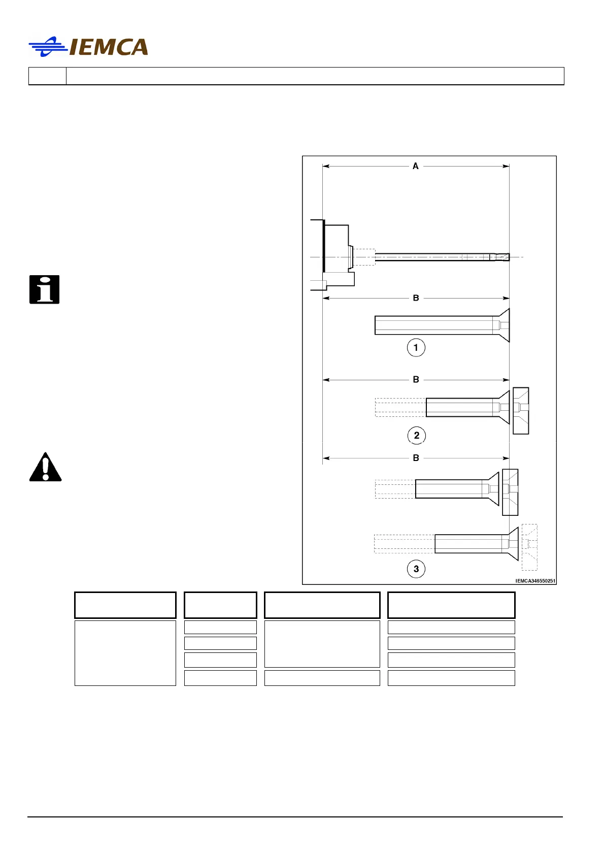
• Place the bar feeder behind the lathe,
considering the fixed and moving
dimensions of both machines. Coupling
distance "B" should not exceed bar pusher
max. extension "A".
1 Fixed headstock or sliding rest lathe
2 Sliding headstock CNC lathe
3 Sliding headstock cam lathe
INFORMATION:
it is not always necessary to drive
the bar pusher all the way out. In
fixed headstock lathes, its stroke
can be reduced to 100 mm to allow
the bar feeder to be brought as close
as possible to the lathe; contact
IEMCA After-sales Service for more
information.
DANGER - WARNING: Perform bar
pusher extension manually. Please,
note that, without the front nose,
the bar feeder might be DANGEROUS
to the operator and/or installation
technician.
Max. bar pusher extension
Model Version Version
A – Max. extension
(mm)
N 937
L 1267
LL
21 - 32 – 37 – 44 - 64
1597
BOSS 332
BOSS 545
BOSS 552 HD
LL + 660 37 – 44 - 64 2257