6 | Installation INFICON
122 / 319 074-594-P1H Micro GC Fusion Operating Man-
ual
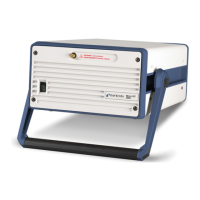
User supplied parts:
• vent tubing and fittings, if used
• 1/8 in. Swagelok type sample input tubing and female fittings
The cap plugs on the sample inlet and the sample vent of the pressure
reducer and gas-liquid separator are not shown in the figure. They must be
removed when performing this installation.
1
Turn off the instrument by following the system shutdown procedure in Shutdown
Procedure [}251].
2
Disconnect all the electrical cables, including the power cable and Ethernet
cable, from the instrument.
3
Disconnect the sample gas connection(s), the carrier gas connection(s) and the
venting connections from the instrument.
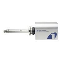
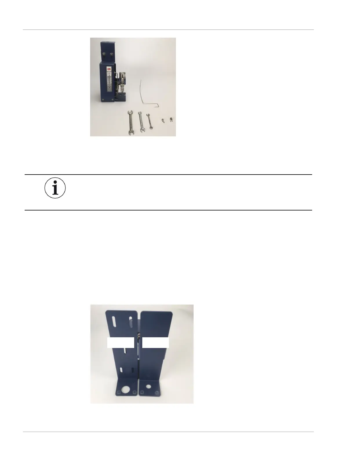
4
Ensure that Bracket C is positioned with two small holes at the bottom when in
the upright position. If not, follow the procedure in Change Mounting Bracket
Orientation [}137] to adjust the mounting bracket orientation.

 Loading...