130 EasyCoder PX4i and PX6i Service Manual
Chapter 13 — Power Supply
6!#
(Z
6$#
0OWER&AIL
4EMP-ONITOR
0OWER3UPPLY"OARD
7STANDBY
7PEEK
-AINS
2ECTIFIER6
#ONTROL6OUT
6
&ORWARD
#ONVERTER
"OOSTER
#ONVERTER
0ULSE7IDTH
-ODULATOR
W0OWER&ACTOR#ONTR
0ULSE7IDTH
-ODULATOR
&ORWARD
4EMPERATURE#ONTROL
0OWER&AIL)NTERRUPT
13.1 Description
The Power Supply Unit (PSU) is identical in all EasyCoder PX4i and
PX6i-series printers. It is situated inside the electronics compartment
between the CPU board and the center section.
No attempt to repair this unit is allowed. Never replace a blown fuse, but
replace the entire PSU.
The power supply unit is primary-switched with power correction factor
controller so as to comply with the CE regulations, which require a sinus-
shaped load curve. It is designed for input voltages in the range of 90 to
265 VAC, 45 to 65Hz. There is no manual switch.
The PSU delivers 20W at standby and 400W peak. Typical consumption
during printing is approximately 100W. The PSU produces 24 VDC only;
all other voltages are transformed from 24 VDC by the driver board and
CPU board. The CPU board controls the PSU over the I
2
C bus via the
driver board, where also identifi cation and error signals are transmitted to
the CPU board. Voltage and temperature are monitored and the unit is
over-current protected.
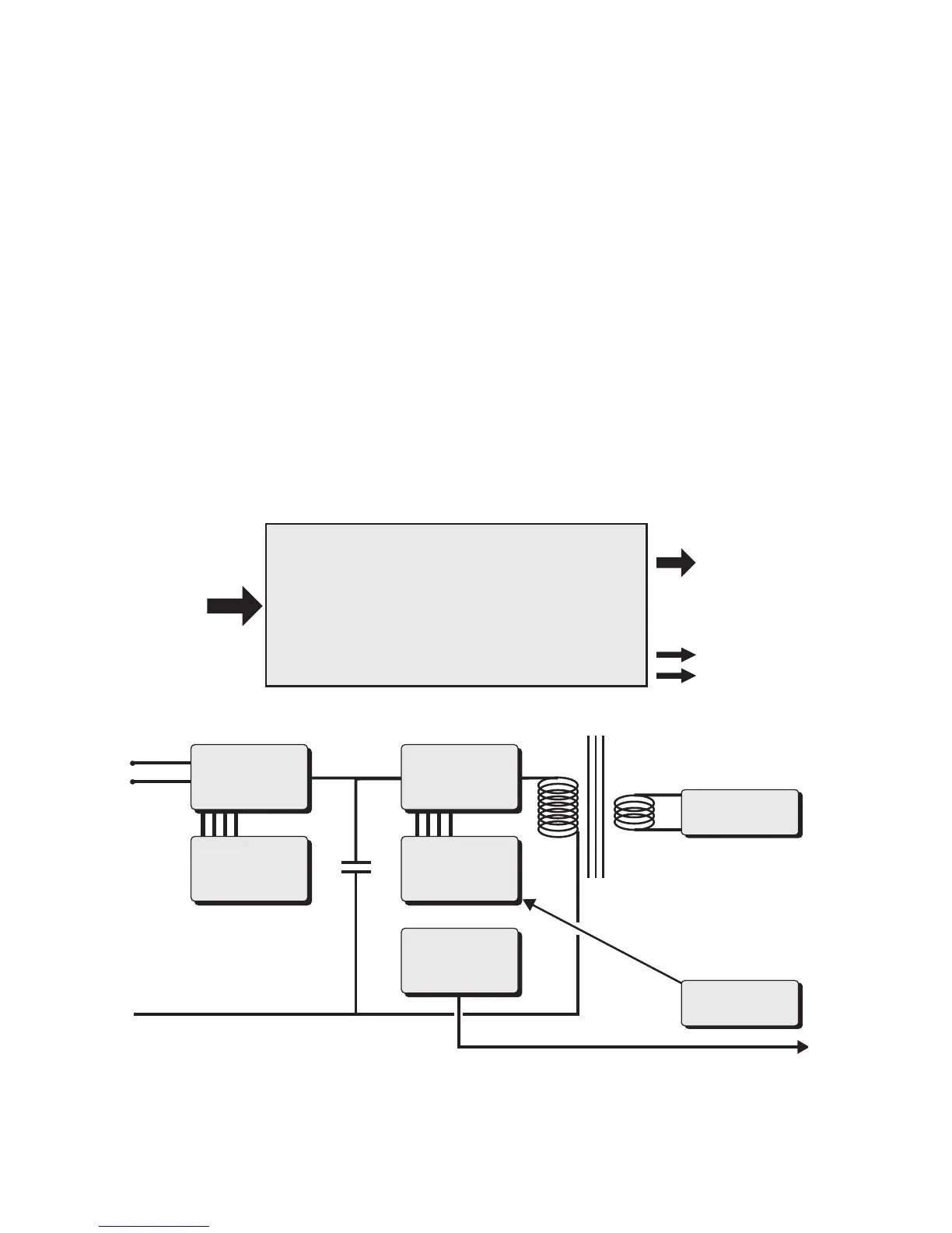
The working principles of the PSU are illustrated by this diagram: