144 EasyCoder PX4i and PX6i Service Manual
Chapter 15 — CPU Board
15.1 Description
The CPU board is a four-layer board with most of its circuits surface-
mounted. Inside the laminate are a combined VCC layer (5V/3.3V/2.5V)
and a GND layer. The front and back sides are signal routing layers.
The hardware contains of the following main functions:
• Processor core
• Thermal printhead driver
• Stepper motor control logic
• Sensor drivers
• Communication, such as UART, USB, etc.
• Flash memory SIMM for the fi rmware and non-volatile storage
• SDRAM SIMM for working memory
• A/D converter for sensor adjustment, etc.
• Compact Flash memory card expansion
• Expansion bus
• PCI bus (custom)
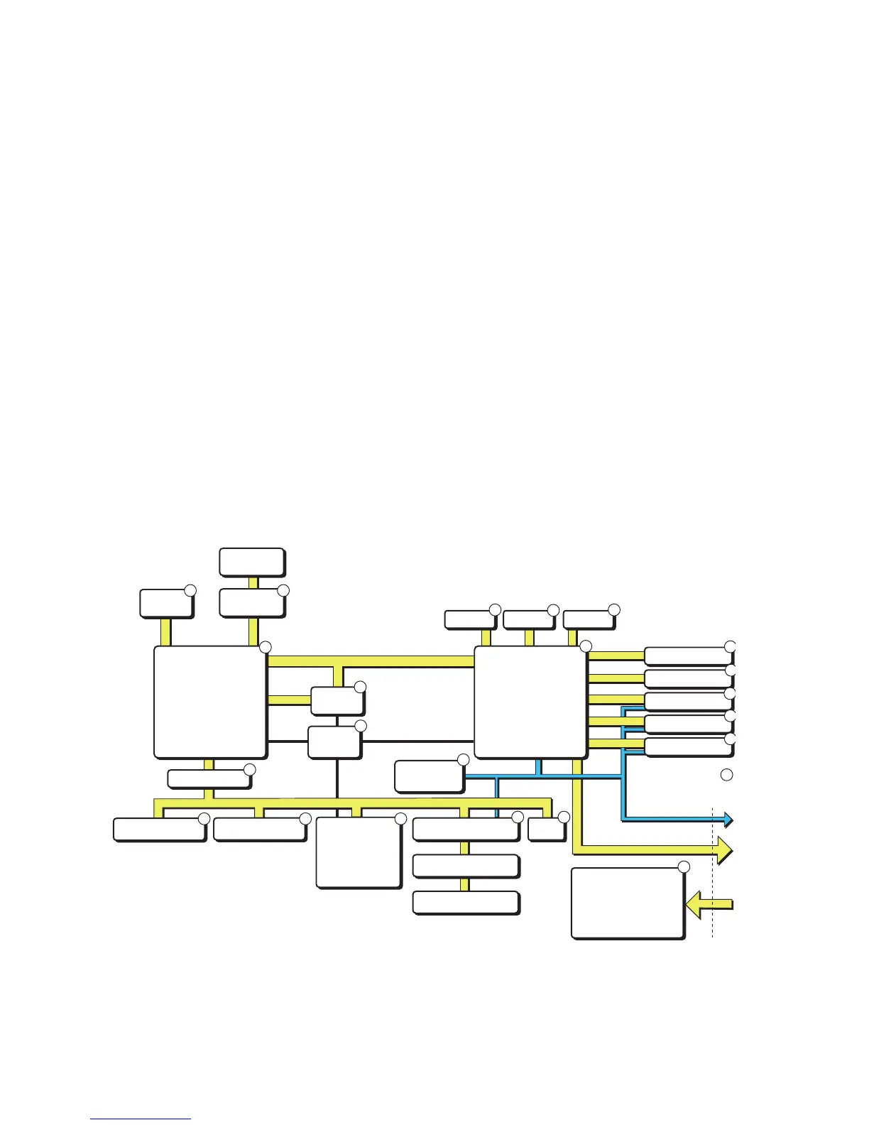
1-971630-26 CPU board; Block Diagram
(numbers refer to schematics in Chapter 15.7)
)
#BUS
0OWERCONVERSION
6
6
6
6)N
3TEPPERCONTROLSIGNALS
ONLYONEOPTIONAL
BOARDIN0&SERIES