EasyCoder PX4i and PX6i Service Manual 17
Chapter 2 — Front and Keyboard
2.2 Keyboard/Display
The keyboard/display assy. is connected to J50 at the front of the CPU
board via a 10-p fl at cable. This cable must be disconnected before the
keyboard/display can be removed.
The keyboard/display must be manipulated carefully when it is lifted out
of its cavity. Do not use any force! If the assembly seems to be stuck, open
the right-hand door and remove the left-hand cover to check that the grub
screws do not interfere with the brackets.
We also recommend you to remove the left-hand cover before you start
to fi t the keyboard/display assy. back into the front moulding, because it
makes it easier to align the brackets with the grub screws.
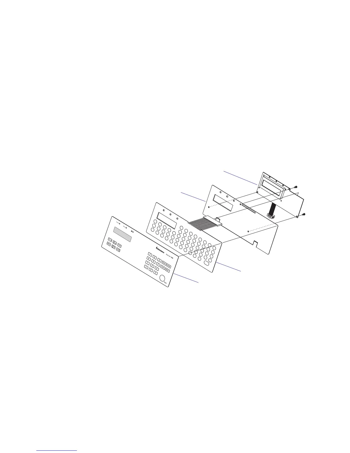
The keyboard/display assy. consists of a plate with two brackets, a self-
adhesive membrane switch keyboard, an self-adhesive overlay, and a
console pcb. The membrane switch keyboard is connected to P2 on the
console pcb. via a semi-transparent cable running through a slot in the
plate.
Membrane-switch
keyboard
Overlay (5 types)
Keyboard plate
Console pcb.