EasyCoder PX4i and PX6i Service Manual 21
Chapter 2 — Front and Keyboard
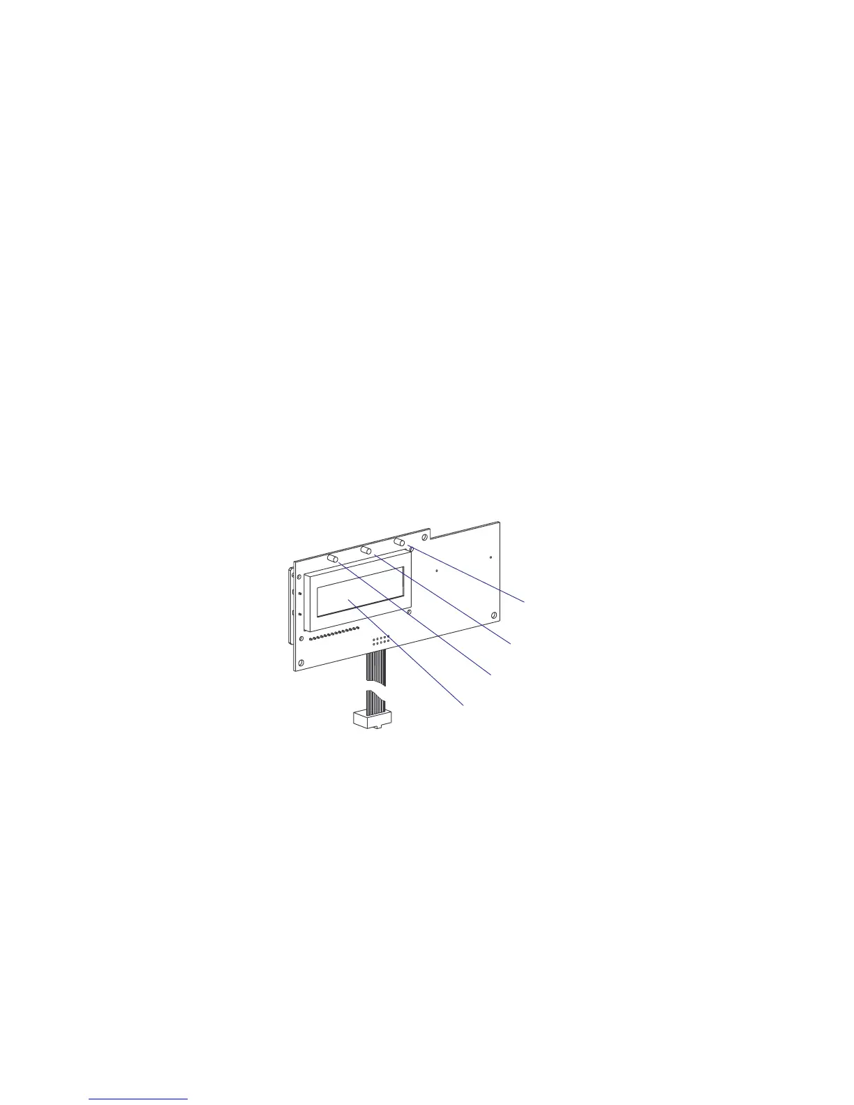
2.3 Console pcb.
The console pcb manages the keyboard, the display and two of the three
LED indicators using a slave processor. The communication to and from
the CPU board goes via an I
2
C bus on a 10-p fl at cable. This cable is per-
manently affi xed to the console pcb and connected to J50 a the front end
of the CPU board.
The display is a LCD display with background light. It has 2 × 16 charac-
ter with a 5 × 7 dots matrix. There is no display contrast adjustment.
The left-hand LED indicator (marked “Power”) shines green when the
power is on. Power on is also indicated by the display’s background light.
The center LED (marked “Status”) is solid green (OK), fl ashing green
(communicating) or solid red (error).
The right-hand LED (Intermec Readiness Indicator) is solid blue, fl ashing
blue, or off which indicates the readiness of the printer to work as a part of
a network solution (see the User’s Guide).
In Fingerprint, the Status LED is programmable using the instructions
LED ON and LED OFF. There is no such functionality in IPL.
Intermec Readiness
Indicator (blue)
Status LED (green or red)
Power On LED (green)
LCD display