170 EasyCoder PX4i and PX6i Service Manual
Chapter 16 — Interfaces
16.5 Installing an Optional Interface Board
To install an optional interface board, proceed according to the step-by-
step instructions below.
Note: This chapter does not apply to installation of any type of EasyLAN
interface board, which instead is described in Chapter 16.9.
• Open the electronics compartment, see Chapter 3.3.
Switch off the power and disconnect the power cord. The electronics
compartment contains high voltage components and wires. Do not open
the electronics compartment before the printer is safely disconnected
from any AC supply.
• Remove the one or two cover plates depending on how many interface
boards you are going to install. Each plate is held by two #T10 Torx
screws. Always start installation at the innermost position.
• Save the cover plate(s) for possible later use. Keep the screws.
• Remove the #T20 Torx screw fi tted on the hexagonal spacer at the
center of the CPU board. Keep the screw.
• If necessary, reconfi gure the interface board by fi tting or removing cir-
cuits and straps according to the descriptions of each board later in this
chapter.
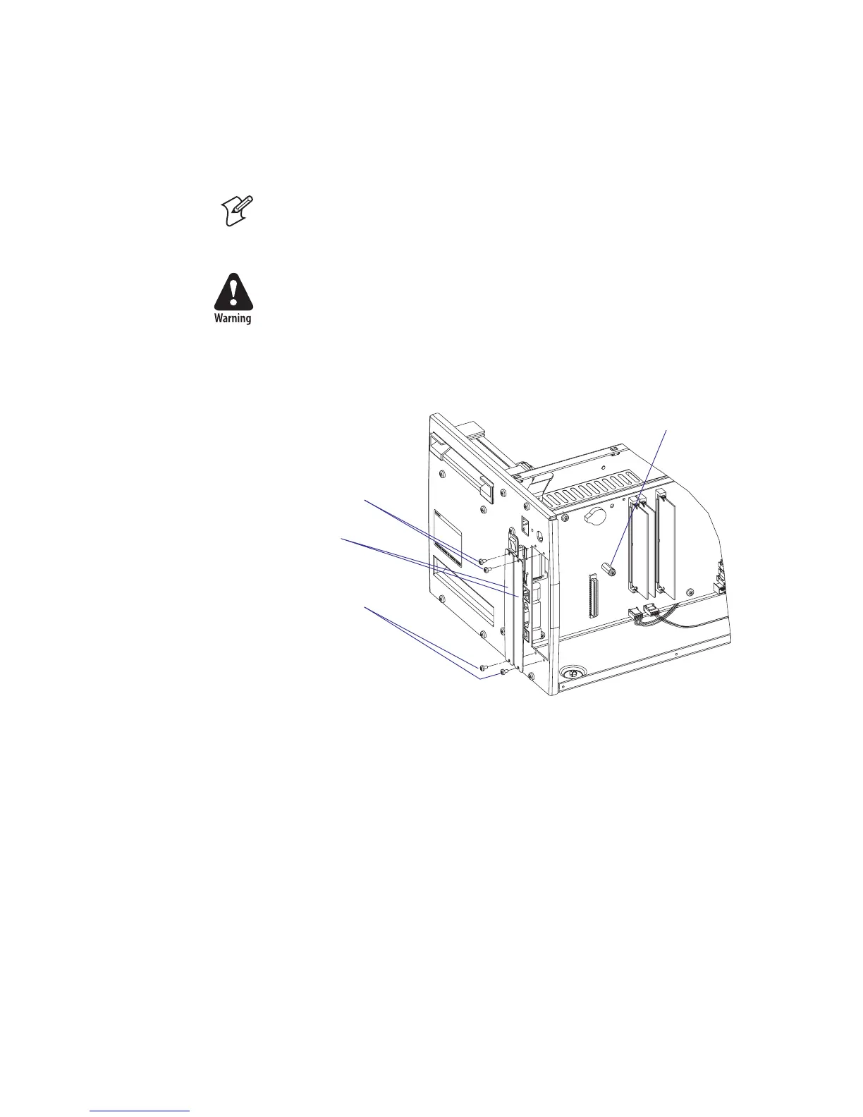
• Attach the fl at cable included in the kit to connector J62 (marked “EXP
BOARD”) on the CPU board (see illustration on the next page).
• Insert the interface board with the component side facing right, as seen
from behind.
#T10 Torx screws
Cover plates
Spacer and screw
#T10 Torx screws