1—
Management panel
3—
Power supply units
2—
Fan modules
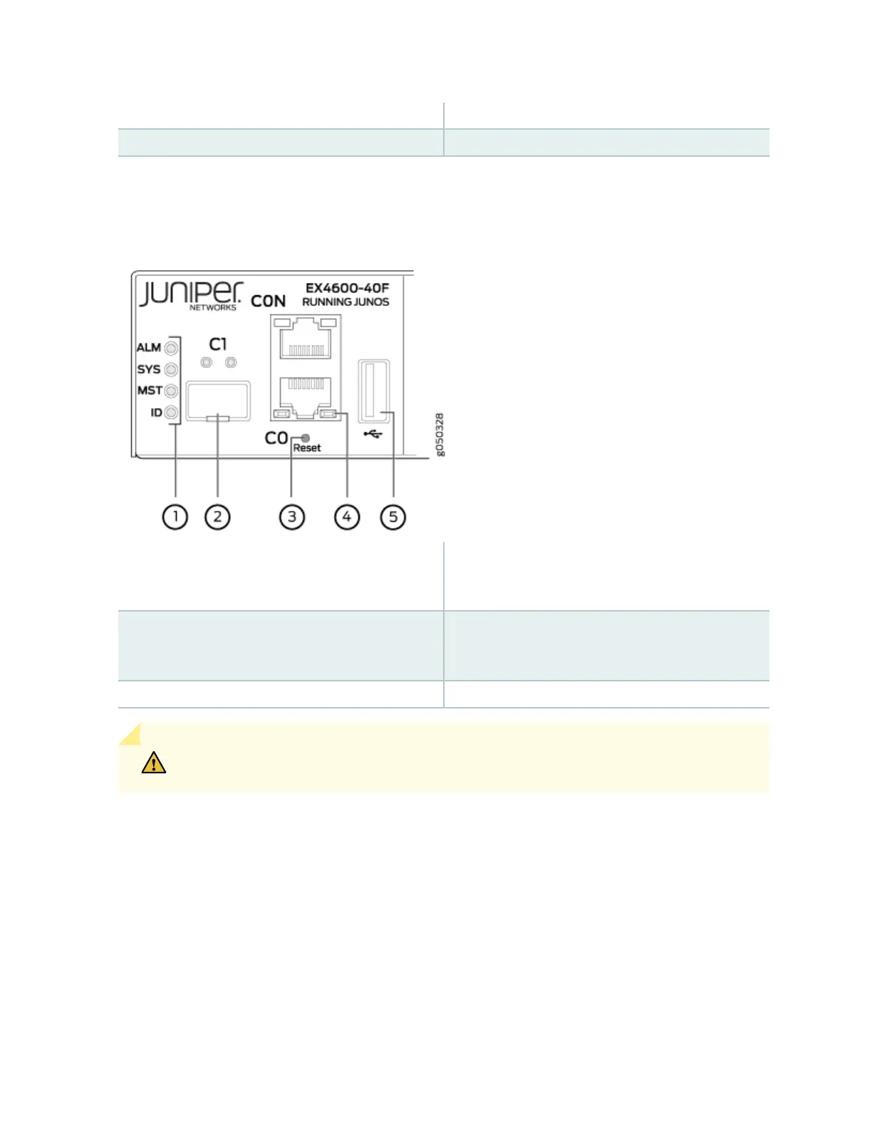
Figure 8: Management Panel Components
1—
Status LEDs
4—
RJ-45 console port (CON) and em0–RJ-45
(1000 Base-T) management Ethernet port
(C0)
2—
em1–SFP management Ethernet port (C1)
Cage (socket for either 1 GbE copper SFP or
ber SFP)
5—
USB port
3—
Reset buon, see cauon statement below
CAUTION: Do not use the Reset buon to restart the power sequence unless under the
direcon of Juniper Networks Technical Assistance Center (JTAC).
The management panel consists of the following components:
• Status LEDs
• ALM (Alarm or beacon)
• Unlit indicates the switch is halted or that there is no alarm.
• Red indicates a major alarm.
• Amber indicates a minor alarm.
14