EasyManuals Logo

Juniper EX4600 Hardware Guide

Juniper EX4600
191 pages
To Next Page IconTo Next Page
To Previous Page IconTo Previous Page
Page #36 background imageLoading...
Page #36 background image
Fan Module LED on an EX4600 Switch
Figure 15 on page 27 shows the locaon of the LED next to the fan module.
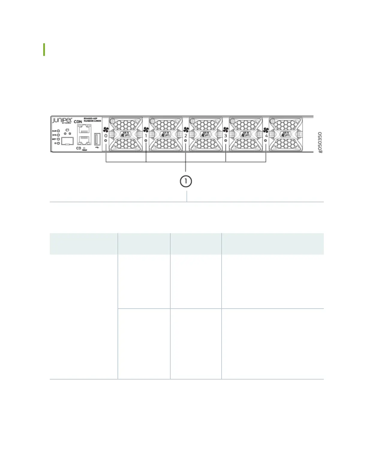
Figure 15: Fan Module LED in an EX4600 Switch
1
Fan LED
Table 11 on page 27 describes the funcon of the fan tray LED.
Table 11: Fan Tray LED in an EX4600 Switch
Name Color State Descripon
Fan Green On steadily The fan module is operang normally.
The system has veried that the module
is engaged, that the airow is in the
correct direcon, and that the fan is
operang correctly.
Amber Blinking An error has been detected in the fan
module. Replace the fan module as soon
as possible. Either the fan has failed or it
is seated incorrectly. To maintain proper
airow through the chassis, leave the
fan module installed in the chassis unl
you are ready to replace it.
27

Table of Contents

Other manuals for Juniper EX4600

Questions and Answers:

Question and Answer IconNeed help?

Do you have a question about the Juniper EX4600 and is the answer not in the manual?

Juniper EX4600 Specifications

General IconGeneral
Rack Units1U
Junos OSYes
Product SeriesEX Series
DRAM8 GB
Flash Memory16 GB
Ports4 x 40GbE QSFP+ ports
Power SupplyDual, hot-swappable
MAC Address Table Size288, 000
Jumbo Frames9216 bytes
Input Voltage100-240 V AC
Operating Temperature0°C to 40°C
Memory8 GB
Storage16 GB

Related product manuals