Chassis Status LEDs on an EX4600 Switch
The EX4600 switch has four status LEDs on the eld-replaceable unit (FRU) end of the chassis, next to
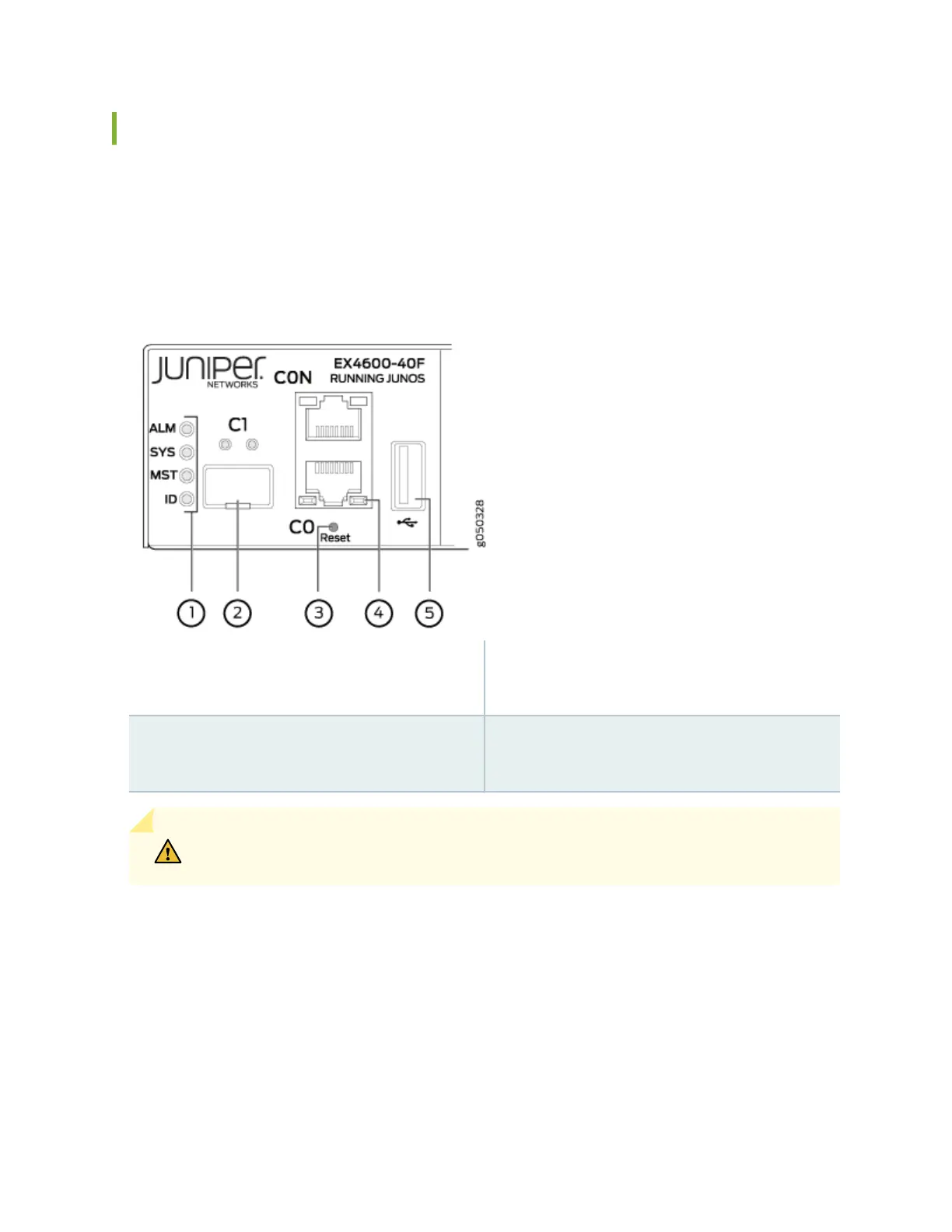
the management ports (see Figure 9 on page 16).
Figure 9: Chassis Status LEDs on an EX4600 Switch
1—
Status LEDs
3—
RJ-45 console port (CON) and em0–RJ-45
(1000 Base-T) management Ethernet port
(C0)
2—
em1–SFP management Ethernet port (C1)
Cage (socket for either 1 GbE copper SFP or
ber SFP)
4—
USB port
CAUTION: Do not use the Reset buon to restart the power sequence unless under the
direcon of Juniper Networks Technical Assistance Center (JTAC).
Table 6 on page 17 describes the chassis status LEDs on an EX4600 switch, their colors and states, and
the status they indicate. You can view the colors of the three LEDs remotely through the CLI by issuing
the operaonal mode command show chassis lcd.
16