port to connect the device to the console server or management console. The console port accepts a
cable that has an RJ-45 connector.
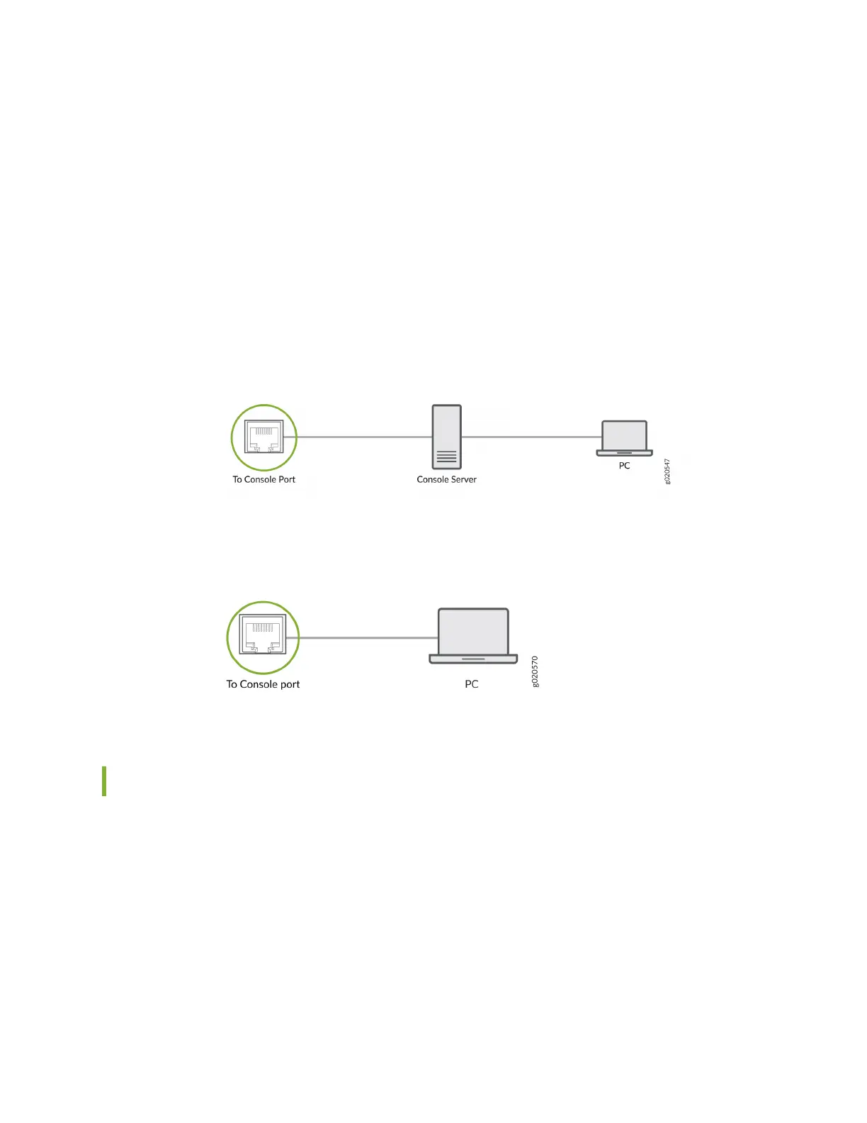
To connect the device to a management console (see Figure 35 on page 89 and Figure 36 on page
89):
1. Connect one end of the Ethernet cable to the console port (labeled CON, CONSOLE, or CON1) on
the device.
2. Connect the other end of the Ethernet cable to the console server (see Figure 35 on page 89) or
management console (see Figure 36 on page 89).
Figure 35: Connect a Device to a Management Console Through a Console Server
Figure 36: Connect a Device Directly to a Management Console
Connecng EX4600 Switches in a Virtual Chassis
EX4600 switches can be cabled together to create a Virtual Chassis in a ring topology. Each Virtual
Chassis can have up to 10 switches (members) parcipang in the ring. The Virtual Chassis can be
comprised of all EX4600 switches lling the primary Roung Engine (RE), backup RE, and linecard roles.
You can also add EX4300 switches to the Virtual Chassis in the primary or backup roles.
Virtual Chassis can be installed in a single rack, mulple rack, or in wire closets.
You congure an EX4600 Virtual Chassis by conguring the SFP+ or QSFP+ interfaces into Virtual
Chassis ports (VCPs). VCPs connect switches together to form a Virtual Chassis, and are responsible for
passing all data and control trac between member switches in the Virtual Chassis. All non-channelized
89