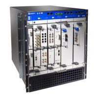
Figure 22: M120 FEB
FEB Components
Each FEB consists of the following components:
•
I-chip ASIC, which provides multiple paths for PFE to PIC communication.
•
H2S—Bridge between HSLA and one SPI4 interface.
•
A crossbar switch that provides connection between the FEB WAN links and the FPC
WAN links.
•
Three LEDs located on the FEB faceplate that display the status of the FEB.
“M120 Forwarding Engine Boards (FEBs) LEDs” on page 77 describes the functions of
the FEB LEDs.
•
Six LEDs located on the FEB faceplate indicate which FPC the FEB is connected to,
labeled 0 through 5. The illuminated green LED corresponds to the FPC connected to
the FEB.
•
Midplane connectors and power circuitry.
•
Maximum 20-Gbps fabric interface.
•
Online/offline button.
Related
Documentation
Replacing an M120 FEB on page 255•
• Troubleshooting M120 FEBs on page 289
• Maintaining the M120 FEBs on page 278
Copyright © 2018, Juniper Networks, Inc.76
M120 Multiservice Edge Router Hardware Guide

 Loading...