Connecting the M120 Router to a Management Console or Auxiliary Device
To use a system console to configure and manage the Routing Engine, connect it to the
appropriate CONSOLE port on the craft interface. To use a laptop, modem, or other
auxiliary device, connect it to the appropriate AUX port on the craft interface. Both ports
accept a cable with an RJ-45 connector. One RJ-45/DB-9 cable is provided with the
router. To connect a device to the other port, you must supply another cable. For cable
specifications, see “Routing Engine Interface Cable and Wire Specifications for the M120
Router” on page 105.
To connect a management console or auxiliary device:
1. Turn off the power to the console or auxiliary device.
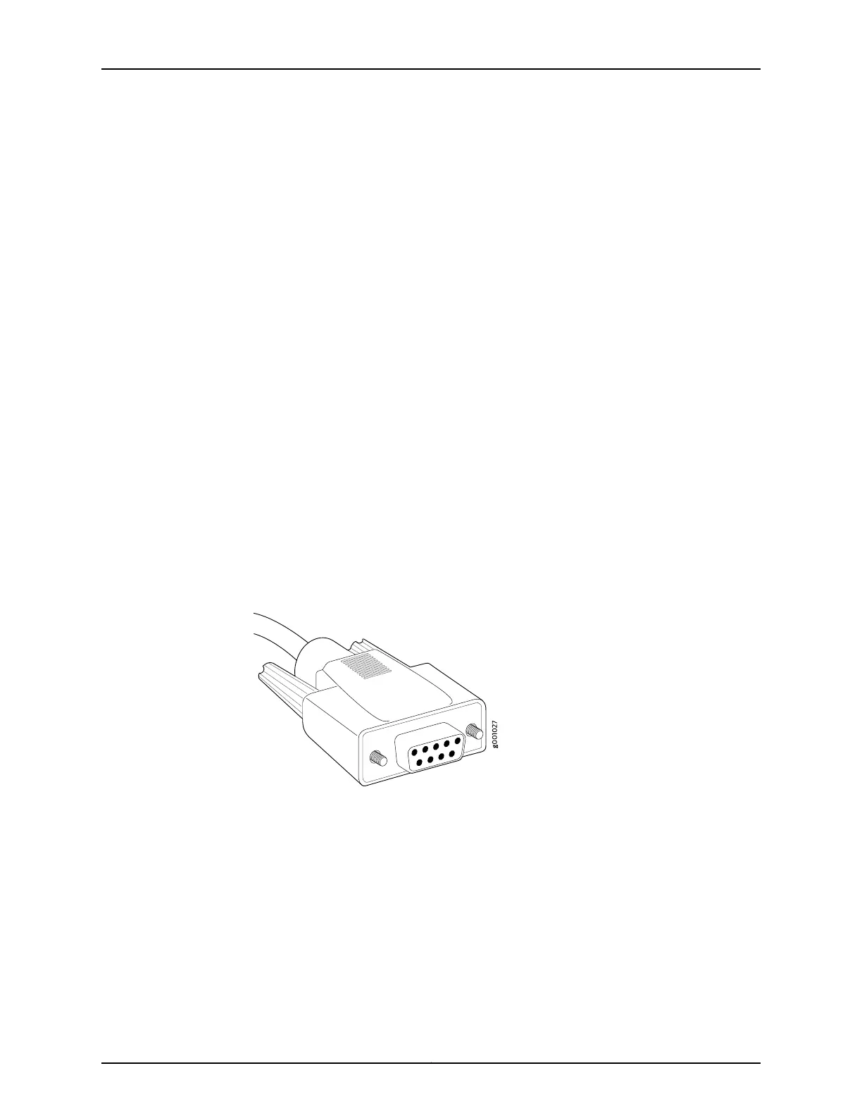
2. Plug the female end (shown in Figure 49 on page 155) of the provided serial cable into
the appropriate CONSOLE or AUX port. Figure 50 on page 156 shows the external device
ports on the CIP. The ports labeled HOST 0 connect to the Routing Engine in the upper
Routing Engine slot (RE 0), and the ports labeled HOST 1 connect to the Routing Engine
in the lower Routing Engine slot (RE 1).
3. Using a 2.5-mm flat-blade screwdriver, tighten the screws on the connector.
4. Attach the other end of the cable to the console or auxiliary device.
Figure 49: M120 Console and Auxiliary Serial Port Connector
155Copyright © 2018, Juniper Networks, Inc.
Chapter 20: Connecting the M120 to External Devices