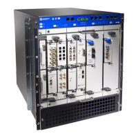
Figure 80: M120 Routing Engine Interface Ports and Alarm Relay Contacts
See Also M120 Alarm Relay Contacts on the Craft Interface on page 17•
• Connecting the M120 Router to an External Alarm-Reporting Device on page 158
• Preventing Electrostatic Discharge Damage to an M120 Router on page 316
• M120 Routing Engine Interface Ports and Status Indicators on page 28
Related
Documentation
M120 Alarm Relay Contacts on the Craft Interface on page 17•
• Connecting the M120 Router to Management and Alarm Devices on page 153
• M120 Fast Ethernet PIC 48-Port Cable Pinouts
• Preventing Electrostatic Discharge Damage to an M120 Router on page 316
• M120 Routing Engine Interface Ports and Status Indicators on page 28
Replacing the Console or Auxiliary Cable on the M120 Routing Engine
To use a system console to configure and manage the Routing Engine, connect it to the
appropriate CONSOLE port on the craft interface. To use a laptop, modem, or other
auxiliary device, connect it to the appropriate AUX port on the craft interface. Both ports
accept a cable with an RJ-45 connector. One RJ-45/DB-9 cable is provided with the
router. To connect a device to the other port, you must supply another cable. For cable
specifications, see “Routing Engine Interface Cable and Wire Specifications for the M120
Router” on page 105.
To connect a management console or auxiliary device:
1. Plug one end of the replacement cable into the appropriate CONSOLE or AUX port.
Figure 79 on page 208 shows the external device ports on the craft interface. The ports
labeled 0 connect to the Routing Engine in the left Routing Engine slot (RE0), and the
ports labeled 1 connect to the Routing Engine in the right Routing Engine slot (RE1).
209Copyright © 2018, Juniper Networks, Inc.
Chapter 26: Replacing Host Subsystem Components

 Loading...