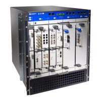
Figure 15: M120 CB
•
CB Components on page 48
CB Components
Each CB consists of the following components:
•
Switch fabric—Provides transit traffic through the Control Board.
•
Control FPGA—Provides the PCI interface to the Routing Engine.
•
1000Base-T Ethernet controller—Provides a 1-Gbps Ethernet link between the Routing
Engines.
•
Ethernet switch—Provides Ethernet connectivity between the Routing Engine and the
FPCs and FEBs; link speeds are 10 Gbps to the Routing Engine and FEBs and 100 Mpbs
to the FPCs and CFPCs.
•
SONET clocking module—Provides a Stratum 3 timing reference for all SONET
interfaces installed in the system.
•
LEDs—Three LEDs on the CB indicate the status of the CB and whether that CB is
master. The LEDs, labeled OK, FAIL, and MSTR are located directly on the control board.
•
Circuits for chassis management and control.
•
Power circuits for the Routing Engine and CB.
•
Offline button—Takes the CB offline when pressed.
Related
Documentation
M120 Control Board (CB) LEDs on page 48•
• Maintaining the M120 Host Subsystem on page 266
• Replacing an M120 CB on page 202
M120 Control Board (CB) LEDs
Table 38 on page 49 describes the functions of the Control Board LEDs.
Copyright © 2018, Juniper Networks, Inc.48
M120 Multiservice Edge Router Hardware Guide

 Loading...