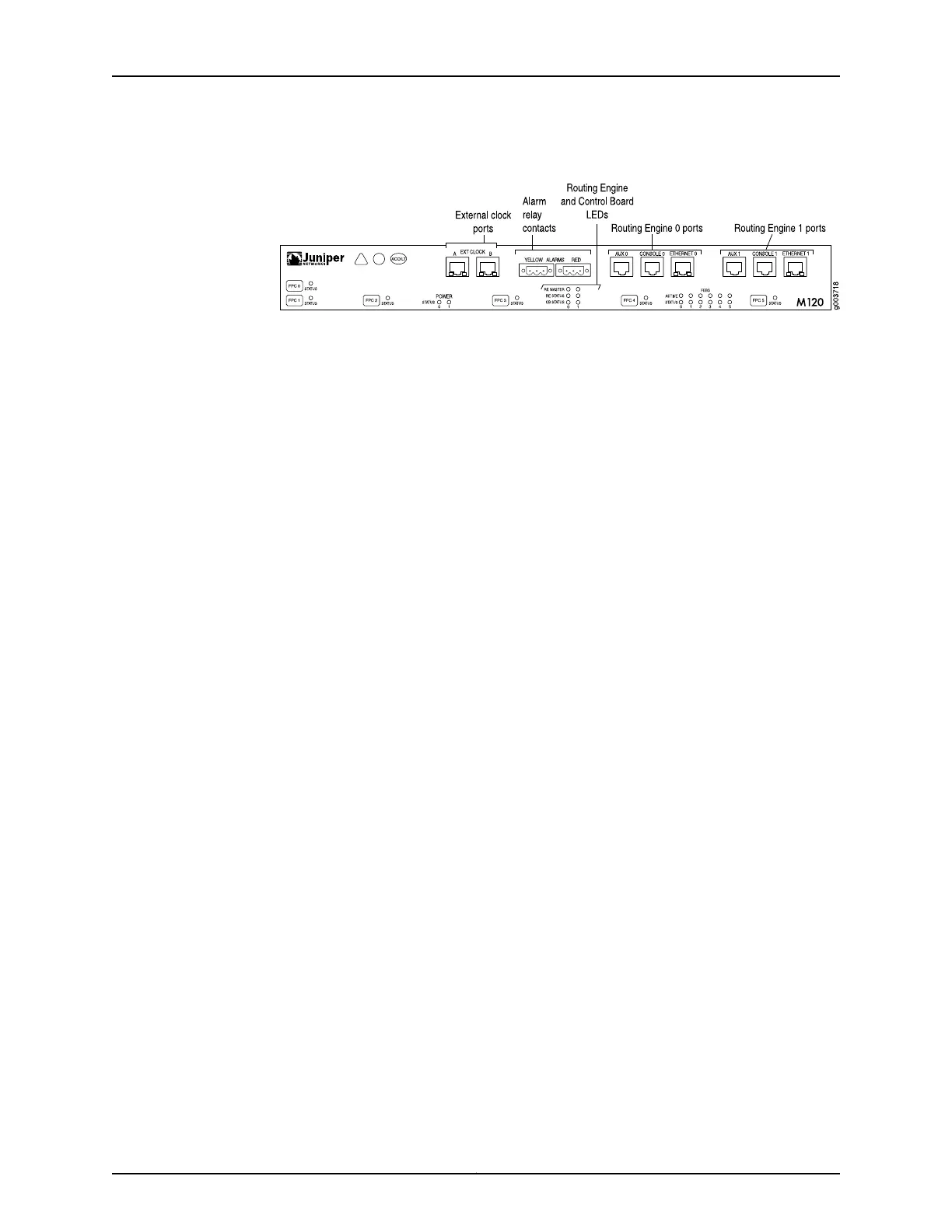
Figure 79: M120 Routing Engine Interface Ports and Alarm Relay Contacts
See Also Connecting the M120 Router to an External Alarm-Reporting Device on page 158•
• Preventing Electrostatic Discharge Damage to an M120 Router on page 316
• M120 Routing Engine Interface Ports and Status Indicators on page 28
Replacing Alarm Relay Wires on the M120 Craft Interface
To connect the router to external alarm-reporting devices, attach wires to the RED and
YELLOW relay contacts on the craft interface. A system condition that triggers the red
or yellow alarm LED on the craft interface also activates the corresponding alarm relay
contact.
The terminal blocks that plug into the alarm relay contacts are supplied with the router.
They accept wire of any gauge between 28-AWG and 14-AWG (0.08 and 2.08 mm
2
),
which is not provided. Use the wire gauge appropriate for the external device you are
connecting.
To replace the wires connecting to an alarm-reporting device (see Figure 60 on page 184):
1. Disconnect the existing wire at the external device.
2. Prepare the required length of replacement wire with gauge between 28-AWG and
14-AWG (0.08 and 2.08 mm
2
).
3. Using a 2.5-mm flat-blade screwdriver, loosen the small screws on the face of the
terminal block and remove the block from the relay contact.
4. Using the 2.5-mm flat-blade screwdriver, loosen the small screws on the side of the
terminal block. Remove existing wires from the slots in the front of the block and insert
replacement wires. Tighten the screws to secure the wire.
5. Plug the terminal block into the relay contact and use a 2.5-mm flat-blade screwdriver
to tighten the screws on the face of the block.
6. Attach the other end of the wires to the external device.
Copyright © 2018, Juniper Networks, Inc.208
M120 Multiservice Edge Router Hardware Guide