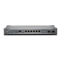
Table 64: Hot-Swappable Component Descriptions for GPIMs
DescriptionComponentNumber
The STATUS LED has the following indicator s:
•
Steady green indicates that the GPIM is functioning normally.
•
Steady yellow indicates that the GPIM is starting up, running
diagnostics, or going offline.
•
Steady red indicates that the GPIM has failed.
•
Off indicates that the GPIM is not powered on, is offline, or is not
configured.
STATUS LED1
NOTE: You need not press this button when installing a GPIM. The
services gateway automatically recognizes when a GPIM has been
inserted into a slot.
ONLINE/OFFLINE button2
Removing a Blank Gigabit-Backplane Physical Interface Module Faceplate
To maintain proper airflow through the services gateway, leave blank faceplates in place over slots that
do not contain Gigabit-Backplane Physical Interface Modules (GPIMs). Do not remove a blank faceplate
unless you are immediately installing a GPIM in the empty slot.
To remove a blank faceplate:
1. Using a Phillips (+) screwdriver, loosen the captive screws on each side of the blank faceplate.
2. Using a flat-blade (–) screwdriver, gently pry out one side of the faceplate and pull it out.
NOTE: When installing a blank GPIM faceplate, make sure that the padded side of the faceplate
is facing up.
Installing a Blank Gigabit-Backplane Physical Interface Module Faceplate
To maintain proper airflow through the services gateway, install blank faceplates in slots that do not contain
Gigabit-Backplane Physical Interface Modules (GPIMs).
To install a blank faceplate:
1. Align the captive screws on the blank faceplate with the screw holes on the chassis.
137

 Loading...