9 Sensor specicaons
145
Notes:
In the United States, installation must be in accordance with the applicable require-
ments of ANSI/ISA RP12.6 and the national electrical code (ANSI/NFPA 70). In
Canada installation must be in accordance with the applicable requirements of Cana-
dian electrical code part I C22.2.1 section 18 and appendix F. Associated Apparatus
manufacturer’s installation drawing shall be followed when installing this equipment.
Ex ia is deined as Intrinsically Safe. The intrinsic safety concept allows the intercon-
nection of two intrinsically safe devices. FM approved and CSA certiied entity para-
meters are not speciically examined in combination as a system when:
Uo or Voc or Vt <= Vmax,
Io or Isc or It <= Imax
Ca or Co >= Ci + Ccable or
La or Lo >= Li + Lcable, Po < Pi.
Control equipment connected to the Associated Apparatus shall not use or generate
more than 250 Vrms or Vdc. Important: Use supply wires suitable for 5 K above
surrounding environment.
For Division 1 installations, the coniguration of Associated Apparatus shall be FM
Approved/CSA Certiied under Entity Concept.
Cables for intrinsically safe installation:
− 10 m (33 ft) cable, part number PR-8230-010, connecting the Indicating transmit-
ter STR/Multichannel user interface MI and the Isolator unit.
The maximum cable length is 100 m (330 ft).
− 10 m (33 ft) power cable, part number PR-8250-010, connecting the Indicating
transmitter STR/Multichannel user interface MI and the Isolator unit, part number
PR-8250-010. The maximum length is 100 m (330 ft).
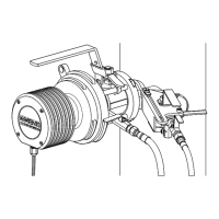
− The intrinsically safe cable between Isolator unit and sensor, part RP-8260-xxx,
where xxx is the cable length in meters. The maximum length is 200 m (660 ft).
For cable connections see Figures 9.38 and 9.41.
Note: Isolator/Barrier Unit can also use an optional external +24V DC power supply
instead of the +24V DC power supply from the transmitter/MI. +24V DC is connected
to terminals 13 and 14. (If +24V DC is used, the PR-8250 power cable is not used at
all.)
9.11.3 Isolator/barriers
Isolator unit wiring is explained below in Figure 9.41.
Note: If the power to Isolator unit terminals is not correctly connected, +24V DC
to terminal 14 (+vs) and zero to terminal 13 (-vs), the transmitter STR/Multichannel
user interface MI will give the message No signal. Also if terminals 11 and 12 are not
correctly connected, sensor cable connecting terminal 2 of the Indicating transmitter
STR/Multichannel user interface MI to the Isolator unit terminal 11 (-ve) and terminal
1 of the STR/MI to Isolator unit terminal 12 (+ve) , the message No signal will appear.
 Loading...