30
PR-23 instrucon manual
6. For a connected sensor, the diagnostic message at start-up should be NORMAL OPERATION
or, if the process pipe is empty, NO SAMPLE. Otherwise, see Section 8.4, “Diagnostic
messages table”.
7. The TEMP value should show the current process temperature.
8. The value and the correct setup of the two mA output signals can be checked by
selecting DESCRIPTION in the Main menu and then mA OUTPUTS in the Description
menu (Section 5.3).
9. If internal relays or switch inputs are used, their settings can also be checked
through the Description menu (Section 5.3).
5.1.2 Calibraon check
Wait until normal process conditions occur. The concentration reading is precali-
brated at delivery and a copy of the Sensor calibration certiicate is inside the Indi-
cating transmitter. If the diagnostic message is NORMAL OPERATION but the concen-
tration reading does not agree with the laboratory results, then consult Section 6.4,
“Calibrating the concentration measurement”.
5.1.3 Tesng prism wash
1. Check that the steam or water washing parts are connected (Section 4.2.2, “Prism
wash systems”).
2. In the Main display, press MENU. Then press 3 (to give the command SENSOR
STATUS). In this Sensor status display by pressing the soft key WASH. If soft key
WASH does not appear, no internal relay is conigured for this purpose.
3. Check the n
D
reading, for a successful wash it must drop below 1.34 during steam
wash and drop to approximately 1.33 during water wash.
Important: Before testing prism wash, check that there is liquid in the pipe in front
of the refractometer sensor.
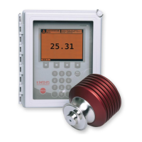
5.2 Using the Indicang transmier
The Indicating transmitter DTR receives the refractive index value n
D
and the process
temperature from the sensor(s). Starting from these values, it calculates the concen-
tration of the process media for display and further transmission. The DTR can also
be programmed to give alarm for high or low concentration. If the refractometer has
a prism wash system, the DTR can control the wash with its built-in timer.
For information on how to use the Indicating transmitter DTR for coniguration and
calibration, see Chapter 6, “Coniguration and calibration”.
 Loading...