3 Indicang transmier DTR
11
The junction box enables the use of customer’s own cable as long as it meets
IEC 61158-2 type A standard requirements, see Section 10.3.2, “Interconnecting cable
speciications”.
3.3.2 Connecng sensor
Important: Sensor connector may not be connected or disconnected when the cir-
cuits are energized. Switch OFF the power from Indicating transmitter DTR external
power switch before disconnecting the sensor cable from the sensor. After connecting
sensor cable back to the sensor you can switch power back on.
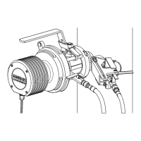
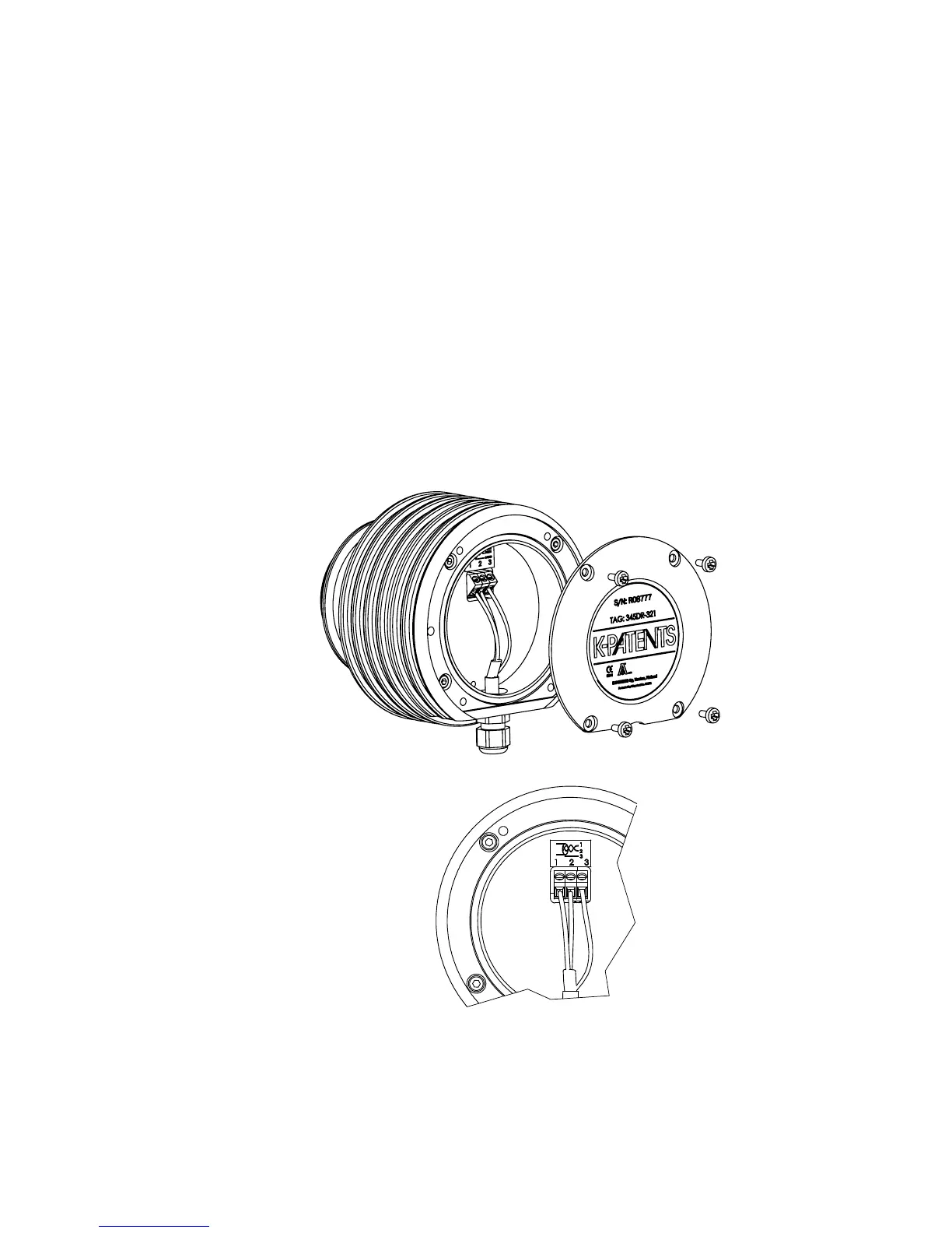
1. Remove the four screws holding the Sensor nameplate (Figure 3.4). The terminal
strip is under the nameplate.
2. Connect the signal wires to terminal (1) and (2), and the cable shield to terminal
(3).
3. Tighten up cable gland. Screw nameplate back on.
Figure 3.4 Sensor electrical connecons
 Loading...