B
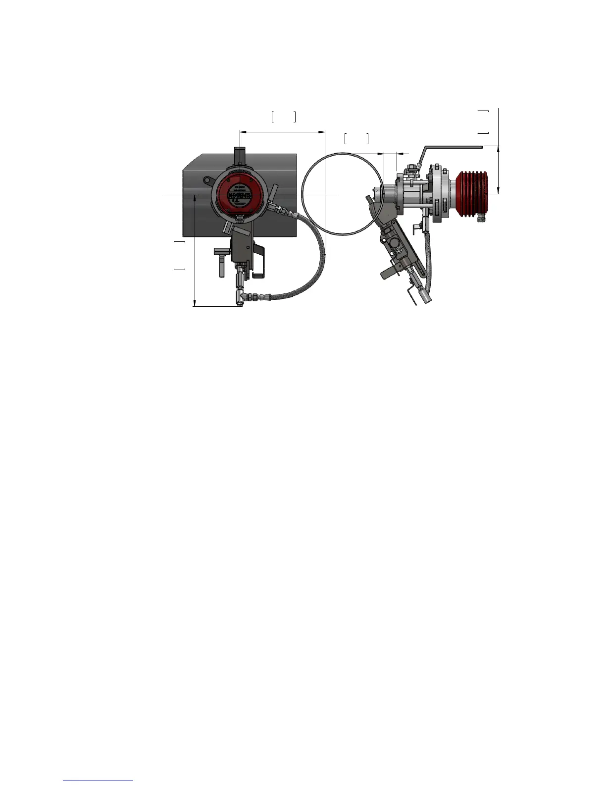
11.60
295
8.86
225
Side view
Top view
1.34
34
5.01
127
F
10.78
274
1.93
49
Related drawing.
No modification permitted
without the approval of
the authorized person.
500 - 1000 [2 - 3 ft]
1000 - 1500 [3 - 6 ft]
Floor or
working platform
Appr.
Drawn
Drawing number
Drawing description
Mass
General tolerances
MTG
27.09.2013 IA
-
Revision
2931
A
Scale
1:5
SDI2 horizontal pipe, space requirement
Material
31.01.2014 AHä
Figure 11.5 Mounng on a horizontal pipe
11.4.1 Welding isolaon valve to pipe
For the Safe-Drive™ Isolation valve, two holes – 50 mm (2") and 25 mm (1") – are
drilled to the pipe and the bridge between the holes is then removed. To help you place
the holes correctly, K-Patents delivers with the valve an installation guide sticker (see
Figure 11.6).
Welding steps (see Figure 11.7 or Figure 11.8):
1. Clean the surface of the pipe around the installation area and place the
guide sticker across the pipe. Make sure that the low marker is parallel
to the pipe and points to the correct low direction.
2. Disassemble the isolation valve for welding to avoid thermal damage to the
isolation valve sealing.
3. Drill 50mm(2") and 25mm (1") holes to pipe and cut the metal away be-
tween the holes.
4. Weld the isolation valve according to MTG472 or MTG2149 (Figure 11.7 or
Figure 11.8)
5. Reassemble the isolation valve. Note! The isolation valve handle and the
large bayonet tooth must be on the top.
6. Tighten the four M10 nuts to the correct torque.
 Loading...