11 Safe-Drive™
167
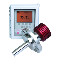
5
1. Insert the safety pin.
2. Lock the safety pin with safety clip.
DO NOT PROCEED UNTIL YOU HAVE COMPLETED THIS
STEP!
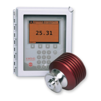
6 1. Close the blow-out ball valve under Isolaon valve.
2. Li up the Isolaon valve handle locking plate.
3. Open Isolaon valve by turning the valve handle 90°.
The valve is open when the ball valve handle is parallel
to Retractor and sensor.
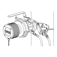
7 Now the sensor can be inserted into the process.
1. Turn the hand-wheel counterclockwise unl it stops,
i.e. unl the sensor ange connects with Isolaon valve
and only the end of the screw thread is visible.
Warning! If you detect leaking, revert immediately to
the previous step. Do not connue the installaon
unl the reason for leakage has been cleared and
xed.
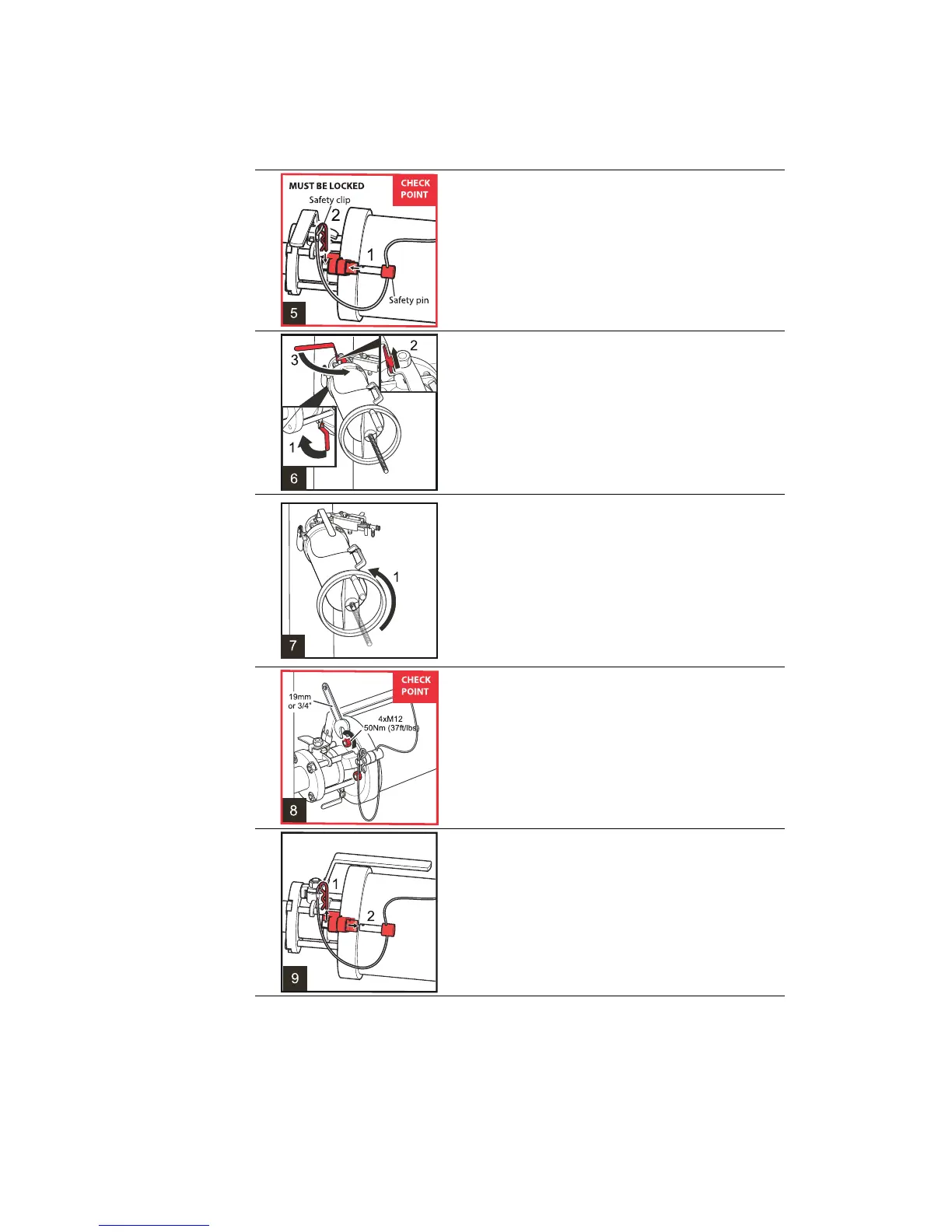
8 Fit the four M12 nuts to the bolts holding the sensor to
Isolaon valve and screw them on with a 19 mm or ¾”
wrench. Important: Do not overghten the nuts, set
the torque at 50 Nm (37 /lbs).
DO NOT PROCEED UNTIL YOU HAVE COMPLETED THIS
STEP!
9 1. Remove the safety clip.
2. Remove the safety pin.
 Loading...