3-36 Keysight B2900 User’s Guide, Edition 5
Installation
Using Digital I/O
Accessory for Digital I/O Connector
The following accessory is available for the Digital I/O connector.
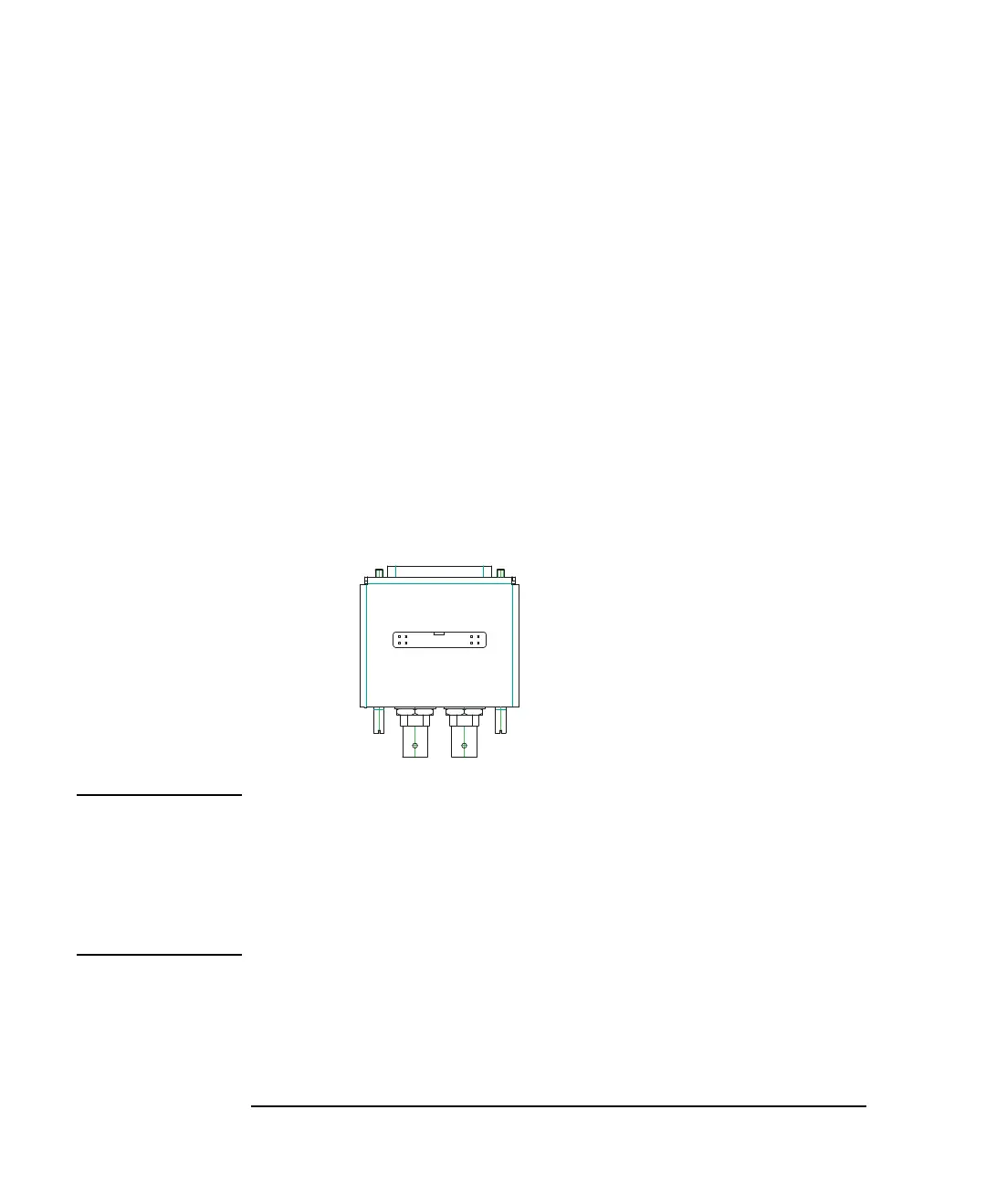
• Keysight N1294A-031 GPIO-BNC Trigger Adapter
This adapter is used to change the Digital I/O connector to the trigger input/
output BNC connectors. The BNC connectors are internally connected to the
DIO pins 9 and 10.
This adapter can be connected directly to the Digital I/O connector.
Figure 3-15 N1294A-031 GPIO-BNC Trigger Adapter
NOTE Interlock terminals
If the N1294A-031 adapter is connected to the Digital I/O connector, the Interlock
terminals are opened. Then the B2961A/B2962A output voltage is limited to 42 V.
To use the interlock function, see “Installing the Interlock Circuit” on page 3-24 and
extend the Interlock terminals. They can be extended from the adapter internal board
through the opening of the adapter top cover.
a. Current limit: 600 mA (total current to the pins 22, 23, and 25)
b. Used for the positive logic. Connected to the pin 25 for the negative
logic.
c. Used for the negative logic. Connected to the pin 17 for the positive
logic.
N1294A Opt 031
GPIO
-
BNC Trigger Adapter
DIO 10 DIO 9