Keysight Technologies N9040B UXA Signal Analyzer Service Guide 387
Assembly Replacement Procedures
RF Area - Options 508, 513, 526
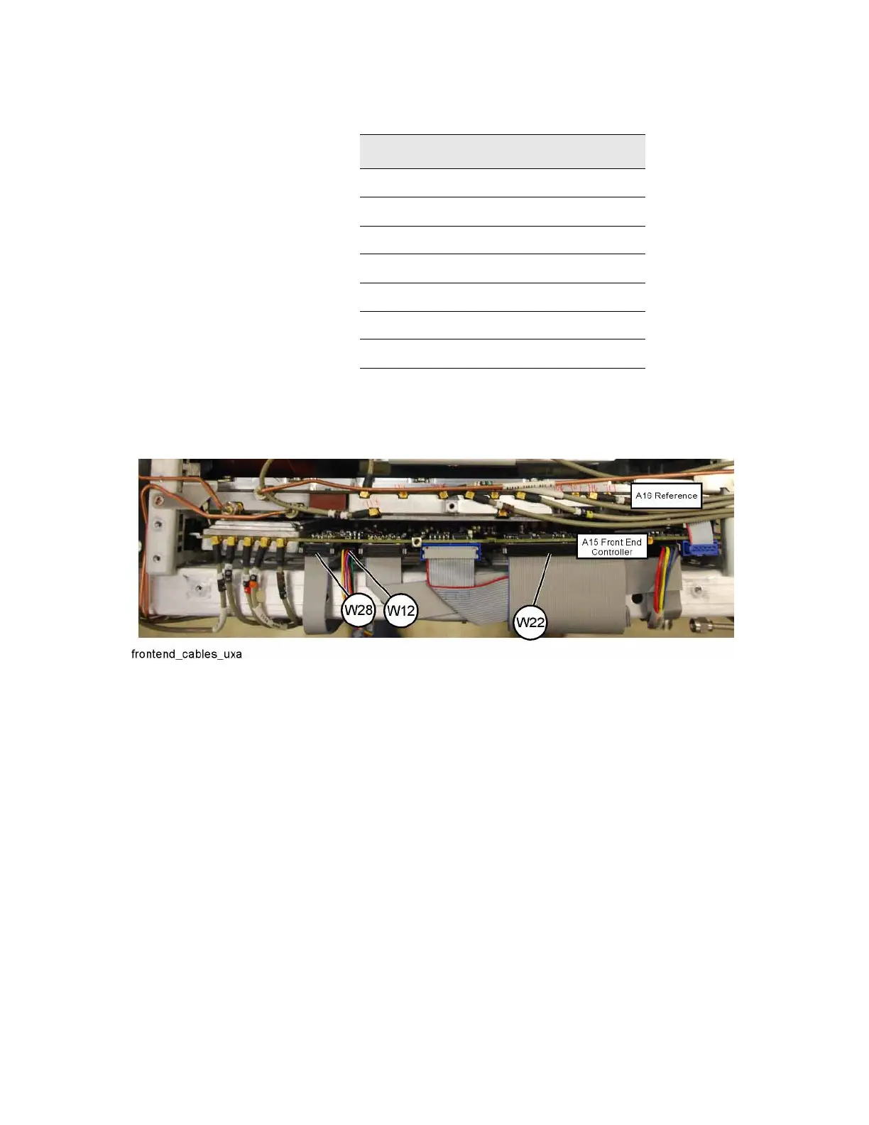
4. Refer to Figure 15-37. Plug ribbon cables W22 and W28, and wire harness
W12 back into the Front End Controller board.
Figure 15-37 Front End Controller Board Cables
5. Perform step 4 through step 7 in the “Low Noise Path and Microwave
Preselector Bypass Switches” replacement procedure on page 377 to
replace the bracket and switch assembly and front brace.
6. Replace the RF bracket, front panel, and instrument outer case as
described on page 360.
Item Keysight Part Number
W8 N9040-20032
W16 8121-2608
W17 N9040-60046
W18 N9040-20039
W21 N9040-20038
W30 8121-1940
W33 8121-1940

 Loading...


