l If you are using a wide aperture (NPLC or aperture mode) and the signal level varies significantly within
the aperture, you may get an unexpected variation in the magnitude of the triggered measurement
from the specified trigger level.
l This parameter is set to its default value after a Factory Reset (*RST) or Instrument Preset
(SYSTem:PRESet).
l
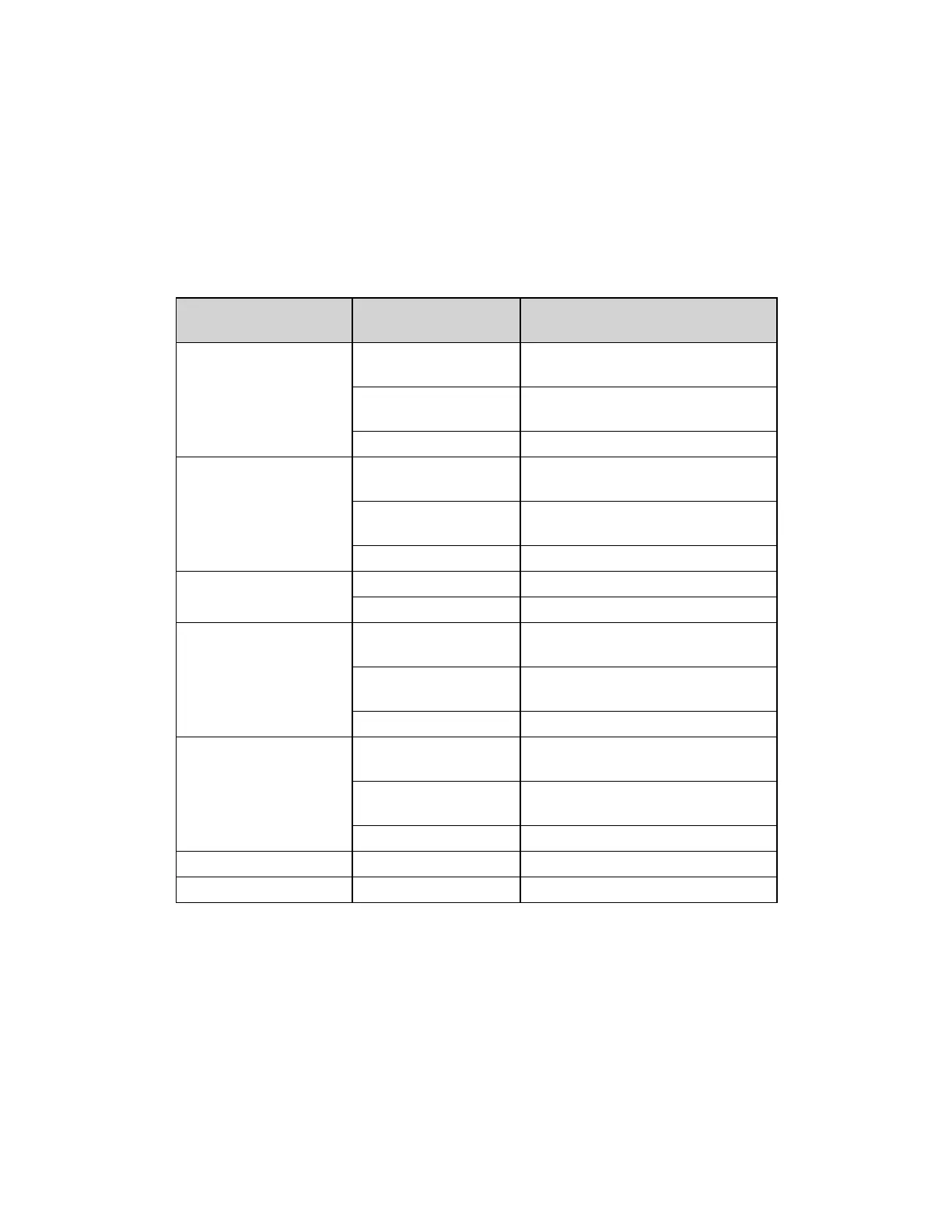
Specify <level> in the fundamental units for the function (volts, ohms, amps, hertz, or seconds). The
table below shows the allowable values for <level> for each measurement function, range, and input
terminals (for DCI and ACI).
Measurement Func-
tion
Range/Input Ter-
minals
<level> Parameter Value
DCV 100 mV to 100 V
ranges, fixed range
±120% of range
1000 V range, fixed
range
±1000 V
Autorange ±1000 V
DCI 3 A terminals, fixed
range
±120% of range
3 A terminals, autor-
ange
±3.6 A
10 A terminals ±12 A
RESistance/FRESistance All ranges, fixed range 0 to +120% of range
Autorange 0 to +1.2 GΩ
ACV 100 mV to 100 V
ranges, fixed range
0 to +120% of range
750 V range, fixed
range
0 to +1000 V
Autorange 0 to +1000 V
ACI 3 A terminals, fixed
range
0 to +120% of range
3 A terminals, autor-
ange
0 to +3.6 A
10 A terminals 0 to +12 A
FREQuency *N/A 3 Hz to 300 kHz
PERiod *N/A 3.33333333 µs to 0.333333333 s
*N/A = Not Applicable.
See Also
TRIGger:DELay
TRIGger:SOURce
Keysight Truevolt Series Operating and Service Guide
431
SCPI Programming Reference