5.9.8 Functional description
In case of use of the STO function the inputs STO1- Enable and STO2-Enable must be
connected to the exits of a security control or a safety relay, which meets at least to the
requirements of the SIL CL2 according to IEC 62061 and PLd according to ISO 13849-1
(see the connection diagrams from page 46).
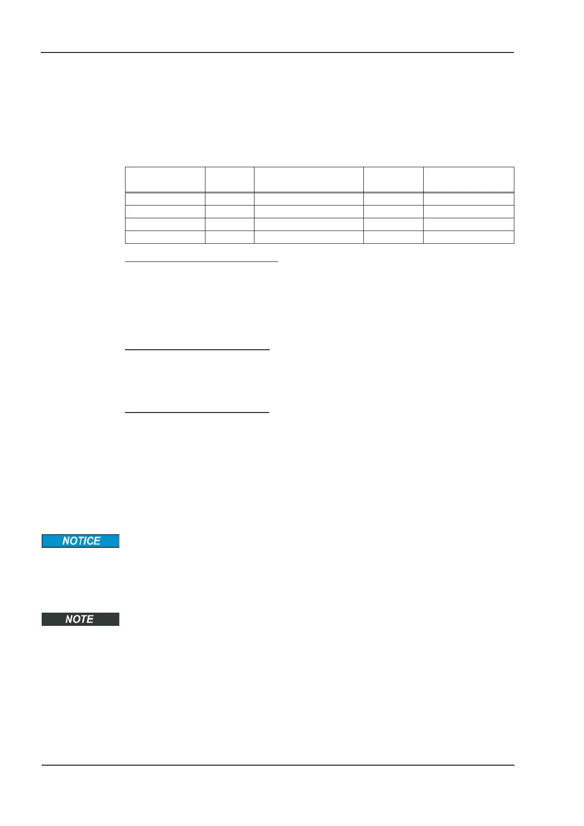
Possible states of the servo amplifier in connection with STO:
STO1-ENABLE
STO2-ENABLE
ENABLE Display
Motor has
torque
SIL CL2 or 3
safety
0 V 0 V -S- no yes
0 V +24 V F27 no yes
+24 V 0 V normal status e.g. 06 no no
+24 V +24 V normal status e.g. E06 yes no
SIL2/PLd Single Channel Control
With the single-channel control of the STO (SIL2/PLd) safety function, both switch-off
paths STO1-Enable and STO2-Enable are switched by one output of a safety switching
device (e.g. safety relay), see example ð p. 46.
In case of single channel usage of STO, erroneous engaging will not be recognized. The-
refore the output of the control must be supervised for possible malfunction.
SIL2/PLd Dual Channel Control
With the dual-channel control of the STO (SIL2/PLd) safety function, the switch-off paths
STO1-Enable and STO2-Enable are switched separately by two outputs of a safety swit-
ching device (e.g. safety relay), see example on ð p. 47.
SIL3/PLe Dual Channel Control
With the dual-channel control of the STO safety function, the switch-off paths
STO1-Enable and STO2-Enable are switched separately by two outputs of a safety con-
trol, see example on ð p. 48.
To achieve PL e or SIL CL3, the safe switching of the pulse inhibitor must be tested peri-
odically by analyzing the feedback signal from the safety control (ð p. 50). The feedback
signal is placed at one of the digital outputs DIGITAL-OUTx (X3A/6 or X3A/7, see p. 101)
of the S700 with the ASCII command OxMODE70.
When wiring the STO inputs within one enclosure it must be paid attention to the fact that
the used cables and the enclosure meet the requirements of IEC 60204-1.
If the wiring leads outside the demanded enclosure, the cables must be laid durably
(firmly), and protected from outside damage (see chapter 5.9.3).
If STO function is not needed in the application, then the inputs STO1-ENABLE and
STO2-ENABLE must be connected directly with +24VDC. STO is passed by now and
cannot be used. Now the servo amplifier is not a safety component referring to the EC
Machine Directive.
44 S701x2-S724x2 Instructions Manual
Technical description 07/2014 Kollmorgen

 Loading...


