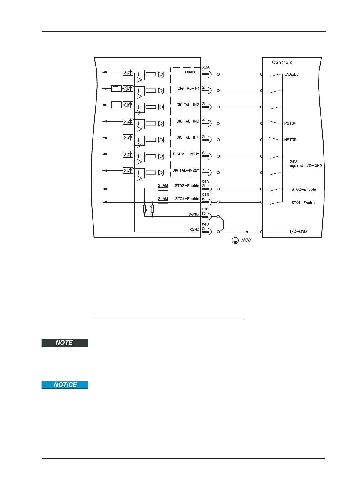
7.15.2 Digital Inputs (X3A, X3B and X4A, X4B)
* DIGITAL-IN 21 and 22 must be defined as inputs using the setup software (“Digital I/O” screen
page).
7.15.2.1 Connector X4A, X4B
You can thus achieve a restart lock-out for functional safety by using the STO1-Enable
and STO2-Enable inputs in conjunction with an external safety circuit.
Input STO1-ENABLE (X4B/6) and STO2-Enable (X4A/3)
— Floating, reference ground is XGND
— 20V...30V / 33mA...40mA
These inputs are not compatible with IEC 61131-2.
These additional digital inputs releases the power output stage of the amplifier as long as
a 24 V signal is applied to these inputs. If the STO inputs go open-circuit, then power will
no longer be supplied to the motor, the drive will lose all torque and coast down to a
stop.
Failsafe braking of the drive, if required, must be provided by means of an additional
mechanical brake, since electrical braking by the drive is no longer possible.
You can find further information and connection examples on page 41ff.
S701x2-S724x2 Instructions Manual 99
Kollmorgen 07/2014 Electrical installation
S700

 Loading...


