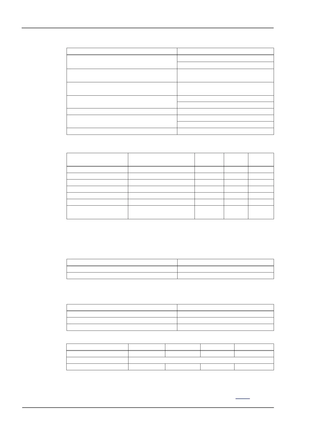
5.2.3 Inputs, outputs, aux. voltage supply
Interface electr. data
Analog inputs 1 and2
±10V
Max. common-mode voltage
±10V
Digital control inputs
as per IEC 61131-2 type1,
max. 30VDC, 15mA
Digital control outputs
as per IEC 61131-2 type1,
max. 30VDC, 100mA
BTB/RTO output, relay contacts
max. 30VDC, max 42VAC
500mA
24V-IO for digital outputs 20V - 30V
Auxiliary supply voltage, electrically isolated 24V (-0% +15%)
current without / with motor brake 1A / 3A
Min./max. output current to brake 0.15A / 2A
5.2.4 Connectors
Connector Type
max. cross
section
*1
permiss.
current
*2
permiss.
voltage
*3
Control signals X3A,B,C Mini-Combicon connector 1,5mm² 4A 160V
Aux. voltage X4A,B Mini-Combicon connector 1,5mm² 4A 160V
Power signals X0, X8, X9 Power-Combicon connector 6mm² 24A 1000V
Resolver input X2 SubD 9pin (socket) 0,5mm² 1A <100V
Encoder input X1 SubD15pin (socket) 0,5mm² 1A <100V
PC interface, CAN X6 SubD 9pin (plug) 0,5mm² 1A <100V
Encoder-Emulation,
ROD/SSI X5 (optional)
SubD 9pin (plug) 0,5mm² 1A <100V
*1 single-line connection
*2 single-line connection with recommended conductor cross section (chapter 5.2.8)
*3 rated voltage with pollution level 2
5.2.5 Recommended tightening torques
Connector Tightening torque
X0, X8, X9 0.7 to 0.8 Nm
Grounding bolt 3.5 Nm
5.2.6 Fusing
Internal fusing, wire fuse or electronic
Circuit Internal fuse
Auxiliary voltage 24V 4A/4A
Brake resistor electronic
STO-Enable 2 A
External fusing by user (US fuses in brackets)
Wire fuses or similar S701 / S703 S706 S712 S724
AC supply feed F
N1/2/3
6 AT (6A)* 10 AT (10A)* 16 AT (15A)* 30/35 AT (30A)*
24V feed F
H1/2
max. 8 AT (8A)
Brake resistor F
B1/2
40 A** 40 A** 40 A** 50 A**
* EU fuses: types gRL or gL, 400V/500V, T means time-delay
US fuses: class RK5 or CC or J or T, 600VAC 200kA, time-delay
** Bussmann FWP-xx
Tips and detailed information can be found in the Product-Wiki on page "Fuses
"
30 S701x2-S724x2 Instructions Manual
Technical description 07/2014 Kollmorgen

 Loading...


